No, there's nothing to worry, but if you want it to be immaculate, you could reduce it the way I told you.
I always prefer it to be within a few mV.
Hans
Finally everything is set up! I'm happy 🙂 Thank you so much Hans!
And I Forgot to ask, how do you think you can improve the sound with more expensive high-quality 1900uf 150v capacitors? Or as long as they don't make any noise, don't touch them? Just in the first versions 27.5 were sprague 1900uf 150v and I have the latest version with nippon ChemiCon 1900uf 150v and they are much cheaper than sprague in the first versions. It bothers me 😁
This is a bit of black magic because in principle a cap is a cap, only the ESR may differ.
Lifetime can be very different from one cap to another, this is reflected in the price.
But because it’s not in the signal path, I find it hard to believe that this Cap could have any influence on the reproduced sound.
Hans
Lifetime can be very different from one cap to another, this is reflected in the price.
But because it’s not in the signal path, I find it hard to believe that this Cap could have any influence on the reproduced sound.
Hans
Last edited:
Congrats regarding your working ML. Don't worry about the 1900uf, don't think they will influence the sound as long as the voltages look smooth.
BR
B. a Hello! You can measure the rest current on your 27.5, I'm just curious �� And direct current at the output terminals
Bias current is 103mA, it was set by a dealer. DC Output is 0,4mV. Sounds like I should crank up my bias a bit.
Hope that helps.
BR
The bias current is 103ma. And at what points did you measure so much? How many millivolts do you have on wh13 and wh14?
That's the total I calculated, I measured voltages over R125+127. Will measure again when I get to it.
BR
PS: do you really think the bass is 'slow'? What speakers do you listen to?
I had a Naim system borrowed, and the kick bass for instance seemed 'harder' and 'faster', more like live when you sit close to the stage, yet a tad 'unnatural', and somehow a bit unpleasant. Prefer the ML.
BR
PS: do you really think the bass is 'slow'? What speakers do you listen to?
I had a Naim system borrowed, and the kick bass for instance seemed 'harder' and 'faster', more like live when you sit close to the stage, yet a tad 'unnatural', and somehow a bit unpleasant. Prefer the ML.
Last edited:
That's the total I calculated, I measured voltages over R125+127. Will measure again when I get to it.
BR
PS: do you really think the bass is 'slow'? What speakers do you listen to?
I had a Naim system borrowed, and the kick bass for instance seemed 'harder' and 'faster', more like live when you sit close to the stage, yet a tad 'unnatural', and somehow a bit unpleasant. Prefer the ML.
Yes, I can't listen to dub and drum and bass DRUM / DUBSTEP too softly, not enough attack. I'm thinking of replacing sprague 674d 680uf 75v with kemet alp22 1000uf 100v, I think it's sprague's fault they seem tired even though they show values from 670 - 900uf.
Everything! Problem solved �� 27.5 warmed up and started to sound fantastic! The dynamics and awesome bass are back! Happy ending ��
Hello, did you replaced the sprague 674d 680uf 75v and after that you got better bass, etc..
Good Morning All,
this seems like the appropriate thread for ML27 question(s)..
I've just acquired a ML27, its in great shape, I collect it tomorrow. It had a few caps replaced about 4 years ago by a dealer up in Sydney, I'd like to check its bias and anything else you folks think I should while I've the covers off.
1/ Could someone please bullet point the bias test procedure, please including test points and confirm if the tests are relative to earth?
2/ I'm yet to visually confirm the Vac in jumpers, the amps rear panel is marked as 210~240Vac, Australian mains is 240Vac. Should I reset the jumpers to 230~250Vac or am I being over cautious? Note I have seen up to 246Vac on mains here!
Many Thanks, Allan
Attachments
well I've sorted Vac in on my 27, the amp starts nicely on 240V & both channels work, however..
today I checked the bias;
left channel is 12.2mV
right channel 24.1mV
(so both channels are out somewhat!)
I also checked the regular current across R114 and R115
Left 1.33V & 1.41Vdc
Right 1.4 & 1.33Vdc
I'm unsure of the way forward here, should I first adjust the regulator current (L&R) and match them better or just re-bias to 17.5mV?
Also, my eyes are playing games seeing the PCB traces... can someone please confirm its the middle pot for bias?

Many Thanks,
Allan
today I checked the bias;
left channel is 12.2mV
right channel 24.1mV
(so both channels are out somewhat!)
I also checked the regular current across R114 and R115
Left 1.33V & 1.41Vdc
Right 1.4 & 1.33Vdc
I'm unsure of the way forward here, should I first adjust the regulator current (L&R) and match them better or just re-bias to 17.5mV?
Also, my eyes are playing games seeing the PCB traces... can someone please confirm its the middle pot for bias?
Many Thanks,
Allan
Hi Allan,
I don't have the ML27 documentation, but only the 27.5.
But apart from a more sophisticated input buffer on the minus input, they are the same.
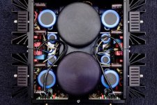
There are three pots as you can see.
Two are for adjusting the Vreg+ and the Vreg- supplying the voltage gain amp with +/- 65Volt
The third pot is for adjusting the bias.
Now the question is which one you should use.
To measure the bias you should use the outer side of the two black resistors on the lower left corner in your picture that are in parallel giving 0.11R and also the outer side of the ones on the right, again 0.11R, so since they are in series you have 0.22R.
For the four complementary output transistors of which each pair should have a bias of 35mA, a total of 140mA should flow through the four black resistors.
so at the outer ends of both you should measure 140mA*(2*0.11R) = 31mV.
I'm pretty sure that the two most outer pots are for Vreg- and Vreg+ and the one in between is for the bias.
When turning this pot carefully while measuring in the corners over the black resistors, you should get immediate feedback that the bias is changing.
If not, take the pot next to is and repeat the process.
Good luck,
Hans
I don't have the ML27 documentation, but only the 27.5.
But apart from a more sophisticated input buffer on the minus input, they are the same.
There are three pots as you can see.
Two are for adjusting the Vreg+ and the Vreg- supplying the voltage gain amp with +/- 65Volt
The third pot is for adjusting the bias.
Now the question is which one you should use.
To measure the bias you should use the outer side of the two black resistors on the lower left corner in your picture that are in parallel giving 0.11R and also the outer side of the ones on the right, again 0.11R, so since they are in series you have 0.22R.
For the four complementary output transistors of which each pair should have a bias of 35mA, a total of 140mA should flow through the four black resistors.
so at the outer ends of both you should measure 140mA*(2*0.11R) = 31mV.
I'm pretty sure that the two most outer pots are for Vreg- and Vreg+ and the one in between is for the bias.
When turning this pot carefully while measuring in the corners over the black resistors, you should get immediate feedback that the bias is changing.
If not, take the pot next to is and repeat the process.
Good luck,
Hans
G'day Hans,
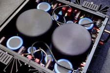
thanks very much for the help here, it biased up nicely.. mid pot.
Prior I had mistakenly adjusted one of the outer pots hoping it was bias when I noticed it changed the DCO, so returned it to its position by DCO.
30min warmup and everything's rock solid. Its sounding very nice, its definitely got more body & drive.
Adj DCO again after the below photo was taken, both L&R now <1.0mV
Bought this amp 16 months ago, it had just been recapped so I'm a bit miffed why the bias was so far out.
Again, thank you")

thanks very much for the help here, it biased up nicely.. mid pot.
Prior I had mistakenly adjusted one of the outer pots hoping it was bias when I noticed it changed the DCO, so returned it to its position by DCO.
30min warmup and everything's rock solid. Its sounding very nice, its definitely got more body & drive.
Adj DCO again after the below photo was taken, both L&R now <1.0mV
Bought this amp 16 months ago, it had just been recapped so I'm a bit miffed why the bias was so far out.
Again, thank you
Hi Hans,Hi Allan,
There are three pots as you can see.
Two are for adjusting the Vreg+ and the Vreg- supplying the voltage gain amp with +/- 65Volt
The third pot is for adjusting the bias.
Good luck,
Hans
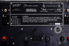
could you verify the test points for adjusting Vreg+ and Vreg- please?
ML27 schematic attached..
The amp is purring along nicely now after re-biasing, heatsink temps are ~8 degC over ambient after 1hr idle and all sinks are within 1 degC of each other. I'd like to check the regulator voltages... icing on the cake!
Thanks Allan
Attachments
- Home
- Amplifiers
- Solid State
- Mark Levinson No.27 amplifier,,,NEED HELP