The discussions around current drive amps has been going on for years, but very few are ever built. Any active speaker with dedicated amps for mid and tweeter might potentially benefit from it, and also FR drivers tends to have a huge benefit from being powered by a current drive amplifier.
In theory, a current drive amplifier is just an amplifier with infinite output impedance. A voltage drive amplifier, on the other hand, is an amplifier with zero output impedance. As all speakers generate their force from current, and not from voltage, having the speaker fed by a controlled voltage is in many senses a step away from controling the driver directly. This is not suitable for all speakers, certainly not if you have 100% current drive, but for some situations, a current drive amp just might be the right choice.
One of the most obvious situations where a current drive power amplifier should be considered is for midrange and tweeter compression driver/horn-combinations. This is sort of the basic idea behind this project, so one of the main focus points is low noise and low distortion. High gain and high power however, is not a priority.
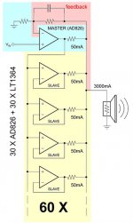
To achieve this, the idea is to stack many small signal op-amps in parallell on each output. By manipulating the balance of the circuit, the level of current drive (or output impedance if you will), the amp is adjustable between current drive and voltage drive. At most, it should be pretty much 100% current drive, and at the other end of the scale, it should be close to 100% voltage drive.
Other priorities are noise (less than 10µV unweighted) and, of course, very low distortion. We are looking at adding local voltage regulators for each op-amp to better achieve this. We are probably looking at upwards to 80W/8 ohm and 160W/4 ohm, but as a current drive amplifier does not increase the power when the impedance is reduced, these numbers are slightly theoretical.
Is this something you guys find interesting? Should I keep you updated on this?
EDIT: And before you post your opinion on why voltage drive is better for a complete loudspeaker. Yes, that is why current drive is only used successfully in active systems, and especially for mid and tweeter, (above Fs) which is also the aim for this project.
In theory, a current drive amplifier is just an amplifier with infinite output impedance. A voltage drive amplifier, on the other hand, is an amplifier with zero output impedance. As all speakers generate their force from current, and not from voltage, having the speaker fed by a controlled voltage is in many senses a step away from controling the driver directly. This is not suitable for all speakers, certainly not if you have 100% current drive, but for some situations, a current drive amp just might be the right choice.
One of the most obvious situations where a current drive power amplifier should be considered is for midrange and tweeter compression driver/horn-combinations. This is sort of the basic idea behind this project, so one of the main focus points is low noise and low distortion. High gain and high power however, is not a priority.
To achieve this, the idea is to stack many small signal op-amps in parallell on each output. By manipulating the balance of the circuit, the level of current drive (or output impedance if you will), the amp is adjustable between current drive and voltage drive. At most, it should be pretty much 100% current drive, and at the other end of the scale, it should be close to 100% voltage drive.
Other priorities are noise (less than 10µV unweighted) and, of course, very low distortion. We are looking at adding local voltage regulators for each op-amp to better achieve this. We are probably looking at upwards to 80W/8 ohm and 160W/4 ohm, but as a current drive amplifier does not increase the power when the impedance is reduced, these numbers are slightly theoretical.
Is this something you guys find interesting? Should I keep you updated on this?
EDIT: And before you post your opinion on why voltage drive is better for a complete loudspeaker. Yes, that is why current drive is only used successfully in active systems, and especially for mid and tweeter, (above Fs) which is also the aim for this project.
Last edited:
Not sure why you would use a ton of small Op Amps, typically able of supplying 5 to 20mA each, and swing between +/- 15V (or less) while you can control a couple regular Power transistors from one Op Amp and achieve same quality and way higher current/voltage/power handling.
Not sure why you would use a ton of small Op Amps, typically able of supplying 5 to 20mA each, and swing between +/- 15V (or less) while you can control a couple regular Power transistors from one Op Amp and achieve same quality and way higher current/voltage/power handling.
There are op-amps with 5-20mA current capability, but there are also several higher current options out there.
In terms of voltage, one could always use bridging. A 36V op-amp in BTL config would be capable of providing enough voltage swing for any high efficiency application.
So why this approach? Simply because it is really good, and to match it with conventional designs, it certainly does not get any cheaper.
I would think an evaluation of existing designs like in the MyRef project would be interesting, then work on a different approach if hugely beneficial.
What existing designs specifically are you referring to?
An Italian member has posted on chip amplifier forum dating may of this year. You can add a current feedback to adjust the output impedance.
That is a very cool way of stacking, but why use this instead of feeding all the op-amps from the same signal directly?
The Italian fellow has studied the question seriously before adventuring in such expensive project. I invite you to read his post Parallel opamp: an extreme audiophile amplifier made of parallel multibrand op-amps
Speakers do not need more than ten times the coil resistance to be current driven . Nowadays 5 ohm is the minimum used for 8 nominal , thus 50 ohms output impedance is sufficient. This can be accomplished by feedbacking the speaker current .
Speakers do not need more than ten times the coil resistance to be current driven . Nowadays 5 ohm is the minimum used for 8 nominal , thus 50 ohms output impedance is sufficient. This can be accomplished by feedbacking the speaker current .
I am curious as to how layout will effect the actual performance.
Me too. The current drop sensors could be integrated into the circuit, but after that, we might just have to add a bit of extra copper as we are moving outside the feedback loop. However, the voltage feedback sensor would be prior to all of this, so it could turn out to benefit from an even stronger path between the op-amps and the current sensor serial resistor.
However, you might have based this on the idea of using very low power op-amps, thinking there will need to be hundereds? Did you see the op-amp Armand points out? The ADA4870 is a beast with 1,2A current limiter.
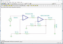
Another option could be the 145mA OPA1622/INA1620, but they are about 30% of the pricing of the ADA4870 so there are no savings here. The suggeste composite setup is indeed interesting with a low noise/high current product as the ADA4870, leaving the precision task to an op-amp like the OPA1622 or similar like this:
Attachments
The Italian fellow has studied the question seriously before adventuring in such expensive project. I invite you to read his post Parallel opamp: an extreme audiophile amplifier made of parallel multibrand op-amps
Speakers do not need more than ten times the coil resistance to be current driven . Nowadays 5 ohm is the minimum used for 8 nominal , thus 50 ohms output impedance is sufficient. This can be accomplished by feedbacking the speaker current .
Thanks for the link. I see he used a rather different approach, limiting himself to through hole components and experiment boards. His selection of op-amps are seriously outperformed by more modern alternatives. Using higher current op-amps as output stage, SMT, of course, and a more compact PCB layout should offer some serious combined advantages.
In terms of current drive, no such general rule will be applicable.
If you run an octave script on FEMM for instance, you can clearly see the huge impact flux modulation has on multi tone signals. But more importantly, what huge differences there are between different drivers. The largest flux modulation impact I have simulated was 319% (which means more than 3/4 of what you hear is flux modulation, while the remaining less than 1/4 is the actual signal). You can remove a fair bit more, even after passign a 10/1 serial resistance. You can emulate voltage as a secondary parameter and feed it back into FEMM as current. That way you can successfully simulate the interaction between two tones.
I have also successfully made a model of a driver modulating less than 3%.
Both of them are not only possible to make, but the first one is pretty close to some existing designs. The second one is a fair bit ahead of the best I have ever seen in existance, but not that hard to make with traditional materials and methods.
These huge flux modulation figures just underline the need for current drive, especially for midrange applications. Could it be that your thumb of rule is not based on the impact of multi tone modulation?
On the other hand I do not believe in using current drive to alter the low end Q for improving bass level.
These huge flux modulation figures just underline the need for current drive,
At last!!!
") I have been stating this in several of the periodic current drive conversations that turn up in this forum - even enduring abusive objections for stating the obvious in my most recent posts.
I have been stating this in several of the periodic current drive conversations that turn up in this forum - even enduring abusive objections for stating the obvious in my most recent posts.IMHO the reduction in third-order harmonic distortion is the biggest advantage of current drive. I have examples of reductions of the order of 40dB in midband distortion, although for better engineered drivers, the effects can be much reduced.
Once the audible distortion has been heard (I liken it to a midband " glare" or "haze"), it is easily identified, even where drivers have been engineered to minimise it. More simply, current drive eliminates it.
But implementations are generally not so simple - which is why current drive comes up here often, but fails to make much progress commercially. Nevertheless, I have posted details in a previous thread of a relatively simple adaption of David Birt's ingenious self-balancing bridge with a floating power supply.
Even then, however, using well-engineered drivers (that is engineered to minimise magnetic non-linearities) helps prevent the need to compensate for distortions finding their way back in via the velocity feedback and making the simple solution not so.
Good to see someone has investigated this issue a bit further Soundbloke.
There are indeed a lot of people having strong opinions, without understanding the inner workings of a magnet system. That is absolutely ok, but opinions are opinions, and must not get in the way of well documented facts.
Anyway, I think the interesting issue here is that the art of developing drivers with virtually no deviation from ideal flux is not something you see every day, or even see at all. Dealing with real life products, especially when the selection is limited to compression drivers of a certain size, you do not have a lot of options, and you certainly do not have a lot of options with advanced motor circuits. Most of the time, you do not find compression drivers with any real focus on these issues. But still, even if you might have a few choices with mor focus on this when dealing with cone midranges, their properties to begin with are far worse, so I am not sure even the very best midranges obtainable would not still benefit hugely from current drive.
In order to understand what current drive is, one needs to understand a little bit about amplifiers. But in order to understand what it does for a driver, one needs to understand the very inner workings of a driver. There are more loudspeaker driver designers that understands enough about amplifiers to understand what current drive is, than there are loudspeaker driver designers that understands enough about magnetics to understand why current drive is good.
Yes! I have posted in threads here on crossovers, equalizers, current drive and more - and each time I always stress that nothing compensates for getting the basic engineering optimized in the first place. The exceptions are few and far between.
I also agree that even the best drivers can benefit: I have a great deal of experience with ATC domes and with Mangers, both of which are outstanding products (although there are applications where the ATCs excel and where the Mangers are just not usable). But both audibly benefit from current drive.
And magnetic circuits do indeed hold a lot of surprises for those who assume some complimentary linearity from a knowledge of their electric counterparts.
Another option could be the 145mA OPA1622/INA1620, but they are about 30% of the pricing of the ADA4870 so there are no savings here. The suggeste composite setup is indeed interesting with a low noise/high current product as the ADA4870, leaving the precision task to an op-amp like the OPA1622 or similar like this:
If you're after a low cost solution it looks hard to beat AD815 as the output buffer. They're under $1 each on Aliexpress and each has 2 * 500mA output current amps inside with very good THD figures.
100% new original AD815ARB 24 AD815ARBZ 24 AD815ARB AD815ARBZ HSOP24-in Integrated Circuits from Electronic Components & Supplies on Aliexpress.com | Alibaba Group
Manger diaphragm is not ideal to me. I have not measured them personally, but the sound is less than optimum slightly on the muffled side which I would attribute to the fact that it operates in the modal mode to generate sound.
It just needs proper crossing over and can be enhanced with a few mods. "Modal mode" makes no sense to me, unless you are talking about the fundamental mode at LF, which i would suggest crossing over above? But it is going off thread.
If you're after a low cost solution it looks hard to beat AD815 as the output buffer. They're under $1 each on Aliexpress and each has 2 * 500mA output current amps inside with very good THD figures.
100% new original AD815ARB 24 AD815ARBZ 24 AD815ARB AD815ARBZ HSOP24-in Integrated Circuits from Electronic Components & Supplies on Aliexpress.com | Alibaba Group
That is a nice one, but it is at EOL, so unless we did purchase a huge pile, it would be a bad idea to design around that. But thanks anyway!
Manger diaphragm is not ideal to me. I have not measured them personally, but the sound is less than optimum slightly on the muffled side which I would attribute to the fact that it operates in the modal mode to generate sound.
There are indeed some shortcomings using that kind of approach, but the work I have done on them does not suggest they are on the muffled side. They can sound really dynamic with a proper edge. The dispersion near the top end could be a bit narrow, so I have suggested ribbon tweeters facing upwards (spreading the sound up and to the left and the right) in order to fill in the empty space in the energy response. I also found that they are best crossed over at above 1,6kHz or so, and indeed not around 500 or lower.
- Home
- Amplifiers
- Solid State
- High performance current drive power amplifier