If you're after a low cost solution it looks hard to beat AD815 as the output buffer. They're under $1 each on Aliexpress and each has 2 * 500mA output current amps inside with very good THD figures.
100% new original AD815ARB 24 AD815ARBZ 24 AD815ARB AD815ARBZ HSOP24-in Integrated Circuits from Electronic Components & Supplies on Aliexpress.com | Alibaba Group
That is an interesting price. 1A and seems to have sufficient BW. Just ordered 10pcs from ebay for a test.
Thank you for the tip.
I can fully understand why you want to build a Current Drive Amp.
But I do not understand why you want to use op-amps with their restricted supply voltage of some +/- 20V max, giving a 12.5Vrms or 19.5 Watt/8 Ohm, quite a distance from the 80W/8 Ohm you are aiming at.
At Fres, depending on the amount and type of damping material used, impedance of a speaker may be quite a bit above the nominal impedance, so maximum voltage output should not restrict this.
Hans
(Your circuit in posting #9 to operate needs the + and - inputs of both amps to be reversed, apart from the fact that this is not configured as a current amp.)
Hi Hans
Bridging then will give the output will give us about 50W/8ohm @ +/- 15V, 72W/8ohm @ +/- 18V, 80W/8ohm @ +/-19V and 89W/8ohm @ +/-20V.
Speakers do not increase their impedance if you use more damping material, but there are other, far more significant reasons for using current drive. Please read the prior posts.
You are right, the op-amps are turned upside down (they are by default) and I forgot to flip them. This is just a principle for using a high power op-amp together with a high precision op-amp, benefiting from the capacity of the high power op-amp and the precision of the other op-amp. A complete current drive amp sure looks different.
This is what it could look like:
I can't understand it either. You need the extra voltage to be able to supply a fixed current through a driver where the impedance can be anywhere from 4 to 40 ohm.


I can't understand it either. You need the extra voltage to be able to supply a fixed current through a driver where the impedance can be anywhere from 4 to 40 ohm.
Why would you want to use current drive on a driver with a 40 ohm impedance peak?
You wouldn't. Perhaps that is why current amps aren't a success. Do you know of any drivers that have a flat impedance? Might be helpful if you plan on doing simulations.
I know I wouldn't. The question was why you would.
You don't need purely resistive drivers to take advantage of current drive amps.
You don't need purely resistive drivers to take advantage of current drive amps.
Hi Hans
Speakers do not increase their impedance if you use more damping material, but there are other, far more significant reasons for using current drive. Please read the prior posts.
You are right, the op-amps are turned upside down (they are by default) and I forgot to flip them. This is just a principle for using a high power op-amp together with a high precision op-amp, benefiting from the capacity of the high power op-amp and the precision of the other op-amp. A complete current drive amp sure looks different.
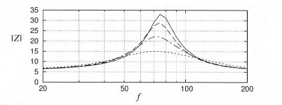
Speakers do not increase but decrease their impedance depending on the amount of damping material. See image below. From top to bottom, no damping, resp. 50% filled with cotton cloth, 80% and fully packed.
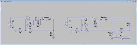
You used a layout where one side of the speaker is connected to ground. A simpler floating version is below with a floating speaker. When going to a bridged solution, the speaker has to flow anyhow.
In the image below a single and a bridged solution. U2 and U4 have to be very fast amps with high supply voltages. U1 and U3 can be low voltage op-amps. U5 can also be a low voltage high current amp, possibly a large number of opamps in parallel.
Hans
Attachments
Off course resonances are damped with damping material. But current drive is most suitable for use with active X-over, working above the fundamental resonance.
I mentioned in a few posts earlier in the thread that the plan is to go for bridging. The schematic was just to show the principle of composite amp. The other schematic shows the principle of current feedback using an op amp and an instrumentation amp.
For a bridged amp, I would prefer a symmetric design. Your designs are a bit hard to make balanced.
O.k, I understand.current drive is most suitable for use with active X-over, working above the fundamental resonance.
Fair enough.For a bridged amp, I would prefer a symmetric design. Your designs are a bit hard to make balanced.
For a Balanced design your circuit in #23 is a better starting point.
Hans
I tested some other options also. Here is one:

And I flipped it around a bit to achieve a closer connection between ground and load:

But as everyone can see, the actual "Hot" output is not the one close to ground. This circuit can't be balanced either.
And I flipped it around a bit to achieve a closer connection between ground and load:
But as everyone can see, the actual "Hot" output is not the one close to ground. This circuit can't be balanced either.
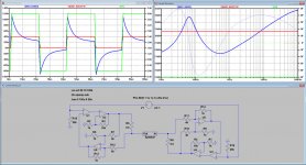
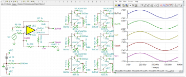
Here an example of a Balanced current amp. Gain is 1/0.25, meaning 4 Amp out / 1 Volt input. Again, U2 and U4 are high speed, high supply and high current amps. The other 4 amps are single fast op-amps. Load is a simulated speaker.
In the image below, Red is the input signal magnified 40 times, Blue is the voltage across the Speaker and green is the current through the Speaker. FR shows a flat spectrum for current whereas the voltage across the speaker shows a curve directly related to its impedance.
In the time response you see a perfect current square wave following the input signal, while the voltage across the speaker follows a complete different path.
Hans
Attachments
This the circuit I have simulated also. By summing local voltage feedback with current feedback around U1and U3 we can mix voltage drive and current drive
That is a 25kHz square wave. What is the upper BW limit here? 1MHz? And then you feed it through a speaker with what? 10mH?
Could you adjust the values to something a bit more realistic?
Could you adjust the values to something a bit more realistic?

If your point is that EMI filtering is important, I totally agree, but as a scenario from real life with high power 1MHz signals, I doubt it serves a useful purpose.
One way of looking at this is by focusing on the waveform. Another way is to view this a 1MHz signal over a large inductor that obviously has very large impedance at such frequencies. We would get the same result using a resistor with the same impedance at 1MHz, and we would also get the same result using the same size resistor at 100Hz.
An amplifier of this kind needs some control circuits. One obvious is a zobel-filter across the load. Another one is input EMI-filtering. But we can not know if the link to the load momentarily breaks, resulting in a sudden voltage peak. For that reason, and several others, we also need a circuit that monitors the output voltage. It could affect the local feedback of the output op-amp turning the amplifier in the direction of a voltage amplifier. Other ways are to limit the voltage, reduce the parallell load, reduce gain and so on.
No, I did not have EMI filtering in mind, I just came with a generic model and did not care about the colour of the interior or the safety belts.
Once agreed upon a design, those things can be added easily.
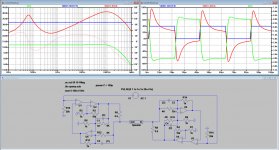
But since you attach great value in having a model with a more normal bandwidth, I have adapted the model to this.
To my opinion, one should concentrate on how to realize U2 and U4, with OPA's or discrete, before going into further details.
Hans
Once agreed upon a design, those things can be added easily.
But since you attach great value in having a model with a more normal bandwidth, I have adapted the model to this.
To my opinion, one should concentrate on how to realize U2 and U4, with OPA's or discrete, before going into further details.
Hans
Attachments
You are probably right about U2/U4, and that is where we have had our focus for a while now. The type of circuit seems to be fairly straight forward. We should also probably look at different places to put HF filtering in the amplifier.
I think one more interesting point here is that if someone puts an amplifier like this on a driver with a serial capacitor for "safety", the amplifier could easily start clipping at lower frequencies. This is a realistic scenario both in terms of what is connected to the outputs, and what signal we could expect.
I think one more interesting point here is that if someone puts an amplifier like this on a driver with a serial capacitor for "safety", the amplifier could easily start clipping at lower frequencies. This is a realistic scenario both in terms of what is connected to the outputs, and what signal we could expect.
Alternative current drive
This is a circuit I have been playing with today using level 3 SPICE models. Much simpler and 100% current drive. Can easily be bridged. In the two attachements everything is equal except the load that is 5 and 10 ohm.
I have collected all the 6 buffers on the right side.
This is a circuit I have been playing with today using level 3 SPICE models. Much simpler and 100% current drive. Can easily be bridged. In the two attachements everything is equal except the load that is 5 and 10 ohm.
I have collected all the 6 buffers on the right side.
Attachments

- Home
- Amplifiers
- Solid State
- High performance current drive power amplifier