I tested the amplifier with both channels for stability for about 8 hours non-stop. The setup was in a hall. The volume was adequate but not the kind of high volume one encounters in dance halls. The main heatsinks remained cold during the entire test. The only ventilation was from a 24V DC fan operating on a supply of 12V DC. The heatsinks fins face each other with a gap of about 1cm in between the heatsinks. The fan sucks air from one end of the heatsinks tunnel thus formed.
Regarding building a small control circuit to drive the fan with a force dependent on temperature, I did not succeed to get the performance I intended. The thermistor becomes active at a far too high temperature. This circuit needs redesign and like before I must be patient to get better results.
Regarding building a small control circuit to drive the fan with a force dependent on temperature, I did not succeed to get the performance I intended. The thermistor becomes active at a far too high temperature. This circuit needs redesign and like before I must be patient to get better results.
OK. So, two comparators with some hysteresis should enable me to define two temperatures to get three operating speeds.
A hysteresis of 5C would be good. How can I get hysteresis without over complicating the circuit?
What I can think I will need for this circuit:
a) a series resistance chain of three resistors with two presets.
b) two resistors for the outputs of both comparators
c) some form of feedback to provide a hysteresis of 5C.
Yes, that's basically how I would do it although I would have to think about how to interface the opamps to the regulator. Little 2N7000 type FET's make really good interface devices as they handle a large gate voltage swing and have low on resistance.
A few different ways of doing it methinks")
A few different ways of doing it methinks
Simplicity is something I am biased to always seek. To this end, I have been mulling about using two transistors to get a continuous motor speed control that depends on temperature. I am posting a circuit that I simulated on LTSpice that seems to give me the required motor operating currents.
These are the consumed currents at various speeds by the motor. I used a variable voltage power supply to measure them.
Motor Speed Vs Current/mA
lowest, 43.1mA
low, 57.6mA
higher but still low, 71.8mA
fast, 110mA
very fast, 152.7mA
The motor is rated at 250mA, 24V DC
Thermistor resistance @ 20C, 13.6kOhm; @ 32C, 10kOhm
In the simulated circuit R4 stands for the motor. R1 stands for the thermistor.
This circuit is the best match I achieved till now.
Attachments
Last edited:
The motor speed controller worked but the fan is too noisy even at slow speeds. Finding an alternative silent fan seems to be the best solution. Suggestions as to from where and which brands I can buy, are most welcome. The fan size is the same as the ones usually found in computer towers.
Fan voltage: 24V DC
Fan voltage: 24V DC
Wouldn't know where to start with that as I've never had to buy any fans. Component suppliers generally have lots available so I guess its a case of wading through data sheets for noise levels and such.
Farnell have over 2000 listed plus they have a noise selector on the page.
Farnell have over 2000 listed plus they have a noise selector on the page.
Attachments
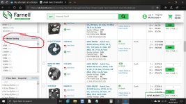
Measuring the fan size I got 80mm x 80mm x 25mm. This is a standard PC fan size.
The vast majority of such fans are of the 12V DC type. Does it make any difference if I use one of these instead of the much rarer 24V DC type? Fitting a silent fan instead of the actual noisy one can help me avoid using a fan speed controller circuit.
The vast majority of such fans are of the 12V DC type. Does it make any difference if I use one of these instead of the much rarer 24V DC type? Fitting a silent fan instead of the actual noisy one can help me avoid using a fan speed controller circuit.
I asked because I had a online UPS that used two 24V DC fans that were very noisy. The fact that this amplifier had a similar noisy fan corroborated my belief that this type of fans are noisy by design. I assumed they spin at higher speeds justifying the use of a higher operating voltage.
I added a small PCB for a negative voltage regulator 7909 with a resistance chain so that the output voltage can be adjusted from around 11V to 13V. The amplifier now does not need more modifications. What is required is installing and connecting a modern 80x80x25 (mm) PC silent fan. I should be able to get one by next Friday. With this done, it will be the end of this project.
It is clear the manufacturer does not want this amplifier to be repaired or modified. The fact that I found resin glue inside the toroidal transformer, on many connectors and under the main reservoir capacitors is a clear corroborate of this belief. However, with great patience, and with the continuous encouragement of Mooly and others, I found the motivation and energy to continue with my seemingly impossible endeavour.
Thanks to all who helped.
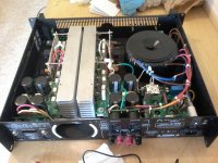
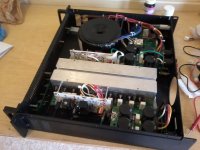
I am attaching two photographs of the amplifier with the upper cover removed.
The white PCBs are mine. The two big ones are installed on stainless steel bolts that are bolted to the two main heatsinks. The tiny PCBs hold the circuitry for the fan's regulators.
Hopefully, this amplifier gives me a very long service.
Thanks to all.
The white PCBs are mine. The two big ones are installed on stainless steel bolts that are bolted to the two main heatsinks. The tiny PCBs hold the circuitry for the fan's regulators.
Hopefully, this amplifier gives me a very long service.
Thanks to all.
Attachments

After trying this amplifier with two large speakers, I found the hum problem is still not resolved. The hum intensity is very low but audible. Remembering the amplifier circuit, the power stage, driver stage and smoothing stages are from the original amplifier circuit and reside on a single PCB. The input stage, VAS and protection circuit lie on another PCB. Both these PCBs are connected with wires (ribbons). The input, VAS and protection PCB takes power from the other PCB, but I did not use any power supply decoupling capacitors. Displacing the signal carrying wires seems to resolve the hum issue. My freedom of taking power from points where there is no coupling from charging current surges is limited by mounting issues.
Hum and buzzes can be hard to eradicate on a completed design... the whole design as a whole has to be considered and with all the potential problem areas attended to.
As avtech says, its been an interesting project and you've done a great job taking it from an idea to a completed design.
As avtech says, its been an interesting project and you've done a great job taking it from an idea to a completed design.
- Home
- Amplifiers
- Solid State
- My attempts at a design of a 3 stage amplifier