As it is, the amplifier can be used, but for an audiophile, this amplifier's noise output should be reduced. Since as it is, the amplifier is useable, I will not commit any physical changes unless I am certain such changes will improve the noise figure.
Please, be patient with me: my technical jargon may not be the standard jargon, and that means, misunderstanding of what I write has an increased probability.
Since there is a large, 2200uF, electrolytic capacitor in the feedback path, it is logical to ask whether this capacitor, that is usually used as a reservoir capacitor in power supplies, is the actual source of noise. I shorted this capacitor in LTSpice, but the DC offset was displaced down to -1.733V. Naturally, this is too high. Somewhere on this same thread, it was mentioned there are ways to add an additional constant DC signal to the input to move the DC offset to 0V. Since, this additional circuit seems to be standard, I do not want to create one myself but use, if necessary, an existing one. A slight positive voltage added to the non-inverting input should remedy the issue.
P.S.
I found this information about capacitors suggesting the latter:
"Capacitors also leak. In theory, a capacitor blocks all DC and passes only AC (including audio). In practice, however, a capacitor will pass some direct current; some types, such as film capacitors, pass almost none, while many electrolytics leak a lot. (Incidentally, most power supply caps leak a great deal when the piece of equipment is first turned on; they stabilize after about 30 minutes, and leak less. This is one of the reasons equipment sounds better after it’s been warmed up.) Replacing capacitors with low-leakage units is always a good idea. Finally, capacitors exhibit a curious behavior called “dielectric absorption,” or “DA.” The capacitor acts as though it has a memory; when a charge is placed on the capacitor, then removed, an echo of the charge can reappear on the plates as if by magic. This can lead to audible problems, including smeared bass notes and the muddied rhythms."
Last edited:
I would doubt the cap is causing any noise but if in doubt then try replacing it with something smaller as a test such as 470uF.
Dielectric absorption is something I've encountered countless times on high voltage caps removed from equipment, and while very real is imo a non problem in audio circuits like this.
A cap that has seen 340 volts DC for years (such as an SMPS reservoir cap) when fully discharged and removed can easily see the terminal voltage creep back up to 60 volts or more.
This is the link for the document I quoted.
Replacing Passive Components to Improve Sound Quality – Bext
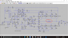
The updated circuit with a DC offset adjusting resistor network is attached. The servo is made of resistors R45, R46 and R47, R46 being a preset. The large electrolytic capacitor is shorted.
Replacing Passive Components to Improve Sound Quality – Bext
The updated circuit with a DC offset adjusting resistor network is attached. The servo is made of resistors R45, R46 and R47, R46 being a preset. The large electrolytic capacitor is shorted.
Attachments
Last edited:
Try a light acting servo. One FET opamp (TL071 is perfect) running on a simple Zener shunt supply.
Try a light acting servo. One FET opamp (TL071 is perfect) running on a simple Zener shunt supply.
I wonder whether the dc issue would arise without R31 adding an extra 2.2k to the inverting input biasing. It seems this could have been resolved or at least abated by removal of R31 and replacing with a link.
I see you have reduced the value of the zener diode feed resistor from 47k to 10k.
Taking this a bit further if the zener is replaced by a resistor e.g. 10k with 100uF in parallel this would bypass zener diode noise if this is the problem source. See below.
Also this would provide some isolation from switching artefacts on the positive supply due to the output transistors at high power levels.
The resistors in question would need to be rescaled to drop the right voltage and sufficient current
Last edited:
Replacing R31 with a 0.1R resistance moved the DC offset further down to -2.117V. Increasing R31 did move the DC offset up towards 0V, but the added values are too big.mjona said:I wonder whether the dc issue would arise without R31 adding an extra 2.2k to the inverting input biasing. It seems this could have been resolved or at least abated by removal of R31 and replacing with a link.
The circuit posted by Mooly is nice, but on a ready built PCB, this is difficult to build. It requires two wirewound dropper resistors from the rails, two Zener diodes and two small smoothing/decoupling capacitors. Besides that, there is the IC and another three components. The IC draws 5mA from both supplies, which means, with voltage droppers from the rails, it will be difficult to make the amplifier work with low voltages.
My solution uses the already existing cascode voltage dropper and 3 resistors one of which is a preset.
I didn't change any resistors 🙂 Just added the servo.
No wirewounds needed... a TL071 consumes little current, just a couple of milliamps. Run the Zener at say 5ma and you have something like a 0.5 watt dropper resistor. Use 18v Zeners and its even better dissipation wise.
And don't forget there are lower power IC's available.
Your circuit already has a 12 volt Zener so that could be the positive rail taken care of.
Your resistive solution is fine though and brings the offset down to low enough levels.
When I shorted the 2200uF capacitor that is in the signal path, the noise intensity decreased, but I used a 10R resistor in series with the speaker to protect it from the -2V DC offset. I know this sounds paranoid, but prevention was always better than cure.
After this step, I removed the capacitor. With the capacitor shorted, LTSpice predicted a DC offset of -1.7V, so simulations and reality seem to be moving together.
Listening to the slight remaining noise, I can hear some weak cracking. I am tempted to attribute this cracking to the electrolytic capacitor across the VBE multiplier.
As I am using half the a.c. supply voltage to the amplifier, mains spikes may not be suppressed properly. By 'spikes' I mean high voltage transients generated by inductive loads being turned off.
Please, ignore the previous post.
As the crackling sound remained, I am concluding the large electrolytic capacitor is not the cause. This conclusion is in accordance with Mooly's belief, and I think, Mooly knows better than me.
Having concluded the above, I restored the circuit to its previous condition by putting back the large electrolytic capacitor together with its four signal diodes.
I have a feeling this problem will be hard to crack, so I must be patient and must admit I am clueless of what can cause it.
The vbe multiplier should be silent in practice, which tbh the feedback should be as well.
I suspect something else is causing what you are hearing. Suppression from external spikes and any RF generated by those spikes is a different kind of problem really and of course you would only hear those spikes when something actually turned on and off.
I suspect something else is causing what you are hearing. Suppression from external spikes and any RF generated by those spikes is a different kind of problem really and of course you would only hear those spikes when something actually turned on and off.
When I shorted the 2200uF capacitor that is in the signal path, the noise intensity decreased, but I used a 10R resistor in series with the speaker to protect it from the -2V DC offset. I know this sounds paranoid, but prevention was always better than cure.
After this step, I removed the capacitor. With the capacitor shorted, LTSpice predicted a DC offset of -1.7V, so simulations and reality seem to be moving together.
Listening to the slight remaining noise, I can hear some weak cracking. I am tempted to attribute this cracking to the electrolytic capacitor across the VBE multiplier.
As I am using half the a.c. supply voltage to the amplifier, mains spikes may not be suppressed properly. By 'spikes' I mean high voltage transients generated by inductive loads being turned off.
My comment was based on Mooly's servo circuit version which does not include the resistors R45-R47 which you added. In so doing you have altered the biasing of the input transistor.
My comment was based on Mooly's servo circuit version which does not include the resistors R45-R47 which you added. In so doing you have altered the biasing of the input transistor.
Note the zener diode is part of this set up you created -and - both the base and collector of the input transistor have connections to this - so you are also introducing some noise from the zener into the base.
The noise resembles the noise from a loose connection. If this is typical of a particular fault, please post.
Nothing really comes to mind.
Does shorting the input alter things? Are you sure it isn't any kind of instability.
Does shorting the input alter things? Are you sure it isn't any kind of instability.
I am not excluding a dry joint since I have been handling the PCB repeatedly for a very long time. Some solder joints are too small, this means a broken soldering joint is quite possible. The power stages emitter resistors come to my mind. Their structure is like a tower and their soldering joints are small. I have no experience with amplifier repair, but I expect a dry joint at a power stage's power transistor may give rise to the crackling plus white noise which I am hearing.
You could do continuity checks to components that connect to earth and see that these are all OK.
There is then the matter whether or not you have followed best practice with routing of the paths.
There is then the matter whether or not you have followed best practice with routing of the paths.
I will power the amplifier and use an insulator stick to lightly touch components. If there is a dry joint, I should be able to hear the amplifier responding to this.
Regarding "best practice" I was always aware signal paths should contain no loops and should be as short as possible. Another thing, is keeping heat sensitive components away from hot components, although even at full power I should not get overly hot components.
This is a teething problem of the several to come until the amplifier is fine-tuned to how I want it. For instance, the unbalanced input is picking a very slight mains hum signal. For this, I will prepare the inputs wiring for balanced inputs, as that was what originally the amplifier had.
It seems I was right, testing is indicating it is a dry joint. The simple test consists of lightly touching the power stage's emitter wirewound resistors. The crackling vanished, only a very low white noise remained. I will resolder the joints.
The next step is a decent XLR input stage. I want to keep the same input impedance as the original, so that, the input boards and wiring behaves as in the original design. By 'behaves', I mean, rejection of parasitic signals.
That sounds promising 🙂 if I'm honest I didn't really think your build would have dries lurking.
It happens to the best of us 😉
It happens to the best of us 😉
The dry joints are not mine, they are from the remainder of the original PCB. Since, these days robots do the soldering, some pads are tiny notwithstanding they are used by wirewound resistors.
Today, I tried the amplifier with higher volumes. Even though I used a cheap speaker as a precaution, the music was pleasant. Usually, I do not use this speaker for high volumes, but with this amplifier the sound reproduction was pleasant to the ear. With these volumes the heatsink became warm.
Regarding the crackling noises, I am still uncertain what precisely was causing them. I know from experience that sensitive circuits do not like the vapour from my hands, even if this is invisible. Some circuits fail to work and I resolve the issue by putting them in the sun to dry. Since there is flux residue, which is organic, this can hold minute amounts of water which can form unstable resistances especially when high voltages are used. Hence the crackling noises
P.S.
Notwithstanding I used a 3m cable to deliver a music signal through an unbalanced input, there was no hum, maybe, a slight inaudible hum but nothing more than that.
One feature of professional amplifiers is they provide XLR inputs. Since I am modifying a professional amplifier, Wharedale S1500, I now prefer to add an XLR input. This must have equal impedances for both the inverting and non-input signal branches. An op-amp with four equal resistors does provide an XLR input stage at unity gain, but that, has different impedances for the two input signal branches. Rejection of interference for such a circuit depends heavily on resistor precision. All four resistors must be equal is value to a very high level of accuracy. This is difficult to achieve as resistors usually have tolerances even reaching 10%.
The dry joints are not mine, they are from the remainder of the original PCB. Since, these days robots do the soldering, some pads are tiny notwithstanding they are used by wirewound resistors......
Ah, OK 🙂 It sounds like you have that issue figured out.
You should be able to get 1% resistors from pretty much any reputable supplier, in fact 1% has been the normal tolerance for low wattage values for quite some time.
- Home
- Amplifiers
- Solid State
- My attempts at a design of a 3 stage amplifier