For some odd reason, many time when professionally measured, they don't find any difference between caps, or just barely. I don't know if we perceive something that is just not measured in their tests or if most of it takes place in our imaginary but I'm pretty sure I can hear a difference. I must also admit that a nice capacitor always looks good in a build! Hehe 😀
Do
Do
For input cap I use Jantzen Supreme on USSA 3 and Alumen on USSA 5. I really like the result. The cap in the BoM is also doing a good job.
Do
I’ve got some Panasonic ECW thin film polypropylene in the right value to hand so I will start with those
I got good results with either ECW-FD2 and ECW-FE2 for low cost input cap. Maybe marginally better with FD2 type.
Fab
Fab
Without pulling them out (currently packing to move house again) I believe I have the FD2 type.
My other choice from those on hand is a Mundorf Supreme something with a diameter of about 50mm and very thick leads << could give it a try but depending on the final casework might not have sufficient room for the overhang! However, mechanically I have not been good with oversize caps as you have to be careful that their weight doesn't break traces or pads if they twist/bend the wrong way if you handle the board.
I'm sure my ears will be happy with the ECW - and I've always loved the look of dipped caps (tropical fish etc.) as they look like sweeties.
My typical choice the for amps Panasonic ECW family, metallized polypropylene. Principals of basic electronics choice of cap if mouser the place ordering from.
Greg:
Although not in the build instructions, it looks like you have coupled transistors Q1/Q2 and Q3/Q4 in your build with heat shrink and something white (thermal grease maybe)? Is this just good practice or something that could impact performance?
Steve
Although not in the build instructions, it looks like you have coupled transistors Q1/Q2 and Q3/Q4 in your build with heat shrink and something white (thermal grease maybe)? Is this just good practice or something that could impact performance?
Steve
HiHi Fab,
Do you ever consider using 2 boards to make a balanced differential amplifier.
No I have never planned for that. In fact I do not have anything balanced in my system. I see it more like a constraint if a real benefit in sound is not easily heard....but I admit that I may need to be educated about that...😎
Fab
The build instructions were done before pcb version 0.4 where the later have complementary transistors close enough to be thermally coupled. I have not tested it but theoretically it is a good thing (dc offset stability) and it should be a marginal improvement in numbers. However I am not sure it can be heard... 🙄Greg:
Although not in the build instructions, it looks like you have coupled transistors Q1/Q2 and Q3/Q4 in your build with heat shrink and something white (thermal grease maybe)? Is this just good practice or something that could impact performance?
Steve
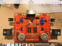
I have only heard version 0.1 of pcb. However, even version 0.1 can have Q1/Q2 thermally coupled with thermal grease and kept together with heat shrink. The distance between the 2 transistors allows to slightly bend the lead of them ...see picture of an USSA-3 board using USSA-5 pcb. Indeed it is good practice in general.
Fab
Attachments
Last edited:
What about Alex build on post your amp #5537. Great 3 channels and 1 for subwoofer. Best so far for value. Do you like it too?
This picture is the USSA-5 amp.What about Alex build on post your amp #5537. Great 3 channels and 1 for subwoofer. Best so far for value. Do you like it too?View attachment 694034
What thread are you referring to?
Fab
Post your Solid State pics here.This picture is the USSA-5 amp.
What thread are you referring to?
Fab
🙂
Thermistor Alternative
While shopping for USSA-5 parts, I came across this Vishay thermistor which is designed to be screw mounted. Yes, a little more cash than what is on the parts list, but I like the fact it mounts with a controlled amount of load.
Steve
While shopping for USSA-5 parts, I came across this Vishay thermistor which is designed to be screw mounted. Yes, a little more cash than what is on the parts list, but I like the fact it mounts with a controlled amount of load.
Steve
Attachments

While shopping for USSA-5 parts, I came across this Vishay thermistor which is designed to be screw mounted. Yes, a little more cash than what is on the parts list, but I like the fact it mounts with a controlled amount of load.
Steve
+1. Great find!
Best,
Anand.
Each thermistor type has their specific temperature profile. You need to compare both profiles and adjust series resistor accordingly to obtain equivalent parallel resistors which bias the driver transistors.
There is no real advantage to have it in contact with heatsink for the purpose. Nelson Pass has it further away from heatsink or transistor than I do in its F5 amp design.
Fab
There is no real advantage to have it in contact with heatsink for the purpose. Nelson Pass has it further away from heatsink or transistor than I do in its F5 amp design.
Fab
Last edited:
Yes, temperature profiles (Resistance vs Temp) need to be the same. Here is a plot (normalized temp coefficient vs temperature) along with raw data for the two different NTC thermistors. As you can see, they are virtually identical. No resistor change is required.
Attachments
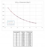
It appears you have made your homework😉Yes, temperature profiles (Resistance vs Temp) need to be the same. Here is a plot (normalized temp coefficient vs temperature) along with raw data for the two different NTC thermistors. As you can see, they are virtually identical. No resistor change is required.
Just ensure to have very short leads on the thermistors to avoid picking up noise.
But again not mandatory to have thermal contact for the thermistors. Thermal contact will increase thermistors temperature that is all.
Fab

Hi Fab
What type of chassis would you recommend ? Is a 3U, 300mm deep ok ?
Thanks
Eric
3U for a class A?🙁
I don't think so.
- Home
- Amplifiers
- Solid State
- USSA-5 Build with Review