In fixing the hum issue by changing the negative lead from C114 from the signal ground (10R lift) to power ground (0v), I took opportunity to put in a big 1000uF cap for the LTP supply smoothing cap. It has a 3sec time constant and what this does is eliminate startup thump on the speaker.
X,
Did you mean C104 100uF?
C114 looks to be an MKS film cap.
Or.... are you performing two changes:
Increase C104 to 1000uF,
Connect the neg side of C114 film cap to the power gnd tab?
Great change X - I strongly endorse to 1000uF for C103.
HD
For HD or X:
Any specific "premium" part recommendations for this Alpha 20W C103 @ 1000uF? PCB will take 10mm diameter with 5mm lead spacing. Presumably anything between the original 47uF and the new 1000uF recommendation is OK?
Also, for Alpha 20W C105/C113, is the SMD 1206 COG as good as it gets, or is a through-hole part better here, C106/C114?
BK
X,
Did you mean C104 100uF?
C114 looks to be an MKS film cap.
Or.... are you performing two changes:
Increase C104 to 1000uF,
Connect the neg side of C114 film cap to the power gnd tab?
Sorry, I meant C104 and negative leg to power ground. It’s a reservoir smoothing cap so “audio grade” caps not required. Anything rated for max +ve tail voltage can work. I happen to have some 1000uF Nichicon 63v in hand. No audio signal passes through it.
Any specific "premium" part recommendations for this Alpha 20W C103 @ 1000uF?
Elna Silmic II 25V,
the 330uF has 5mm spacing and 12.5 diameter,
1000uf is 7.5mm and 16mm, so it will hang a little above the board,
but still manageable I think.
For HD or X:
Any specific "premium" part recommendations for this Alpha 20W C103 @ 1000uF? PCB will take 10mm diameter with 5mm lead spacing. Presumably anything between the original 47uF and the new 1000uF recommendation is OK?
Also, for Alpha 20W C105/C113, is the SMD 1206 COG as good as it gets, or is a through-hole part better here, C106/C114?
BK
Any brand of 1000uF can work as no audio passes through it. Just make use it’s at least 35v preferably 50v rated for B.B. and 35v for Alpha 20.
For the Alpha 20 I have personally found slightly lower distortion (on Aksa Lender Preamp) when using Murata SMT NP0/C0G caps than similar value radial silver mica caps. They don’t have a long lead or extra solder joint and are smaller.
So did all Alpha builders experience hum they now can solve ?
I believe some amplifier upgrades give the front end an entire separate psu, so maybe the 1000uF goes a little that way too ?
I believe some amplifier upgrades give the front end an entire separate psu, so maybe the 1000uF goes a little that way too ?
No it was topology error on my part. In adding a ground lift, I mistakenly connected the lift to C104. When this is done, the “stiffness” of the smoothing cap is now 10ohms or sloppy and soft. So rail ripple is directly impressed on this cap. When connected relative to power ground the rail ripple is absorbed by the intrinsic ESR (typical 60mOhm vs 10ohms with incorrect grounding). Only 47uF is needed to sufficiently smooth the ripple here over the 3k3 upstream. The change to 1000uF was purely to make it slow to charge up so that turn-on rhunpnis now passively eliminated without need for a delay relay. The Alpha 20 has no ground lift and no hum issues. Changing C104 to 1000uF simply eliminates turn-on thump.
Ch 2 progress
Ok, so I fixed the capacitor C104 negative pin to power GND and changed to 1000uF 63v Nichicon, swapped out the source resistors for qnty 4 x 0.22R series-parallel for 0.22R at 12 watts, and installed the big IXYS MOSFETs. Ready to install the CPU coolers now with ceramic pads and heatsink paste compound.
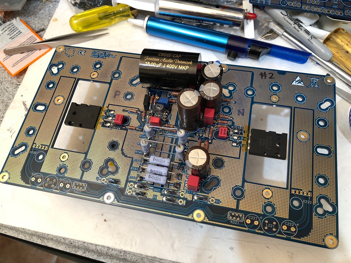

Now have some dinner, and return to finalize and hopefully fire it up and get some sound later tonight on channel 2. Still need to assemble the terminal blocks and trafo and CRC for channel 2 in order to go stereo. Ran out of crimp ring terminals for attaching to terminal blocks. Will need to improvise...
Ok, so I fixed the capacitor C104 negative pin to power GND and changed to 1000uF 63v Nichicon, swapped out the source resistors for qnty 4 x 0.22R series-parallel for 0.22R at 12 watts, and installed the big IXYS MOSFETs. Ready to install the CPU coolers now with ceramic pads and heatsink paste compound.
Now have some dinner, and return to finalize and hopefully fire it up and get some sound later tonight on channel 2. Still need to assemble the terminal blocks and trafo and CRC for channel 2 in order to go stereo. Ran out of crimp ring terminals for attaching to terminal blocks. Will need to improvise...
Attachments
I received the transistors, Thank you!
It was very fast to Toronto.
Greetings
I think I posted at the wrong places...
It was very fast to Toronto.
Greetings
I think I posted at the wrong places...
X,
The design mistake was me, not you! I think your progress here is impeccable, and to amuse all of us, blameless....
No change to the COG snubber C106/C114. Selected components here are just fine.
Yes, two changes: Increase BB C104 from 47uF to 1000uF 25VW is fine here because it never sees more than 10V. 10mm OD 5ps is best, and choose rated to 105C. It DOES NOT NEED TO BE AUDIO GRADE. It does not pass signal at all; it's just removing ripple, nothing more.
X, enjoy your dinner!
HD
I received the transistors, Thank you!
It was very fast to Toronto.
Greetings
I think I posted at the wrong places...
Wow, that was fast (matched KSA992). Good luck with the build!
BK
ALPHA BB Ch 2 First Sound
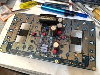
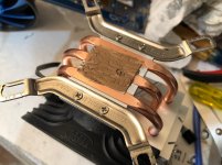
The second channel buildup goes so much easier because of lessons learned from the first one. Here are some details of the heatsink with ceramic insulator pad and heatsink compound (gold colored).
Here is a closeup of the paste on the insulator pad on top of the CPU cooler heat transfer surface:

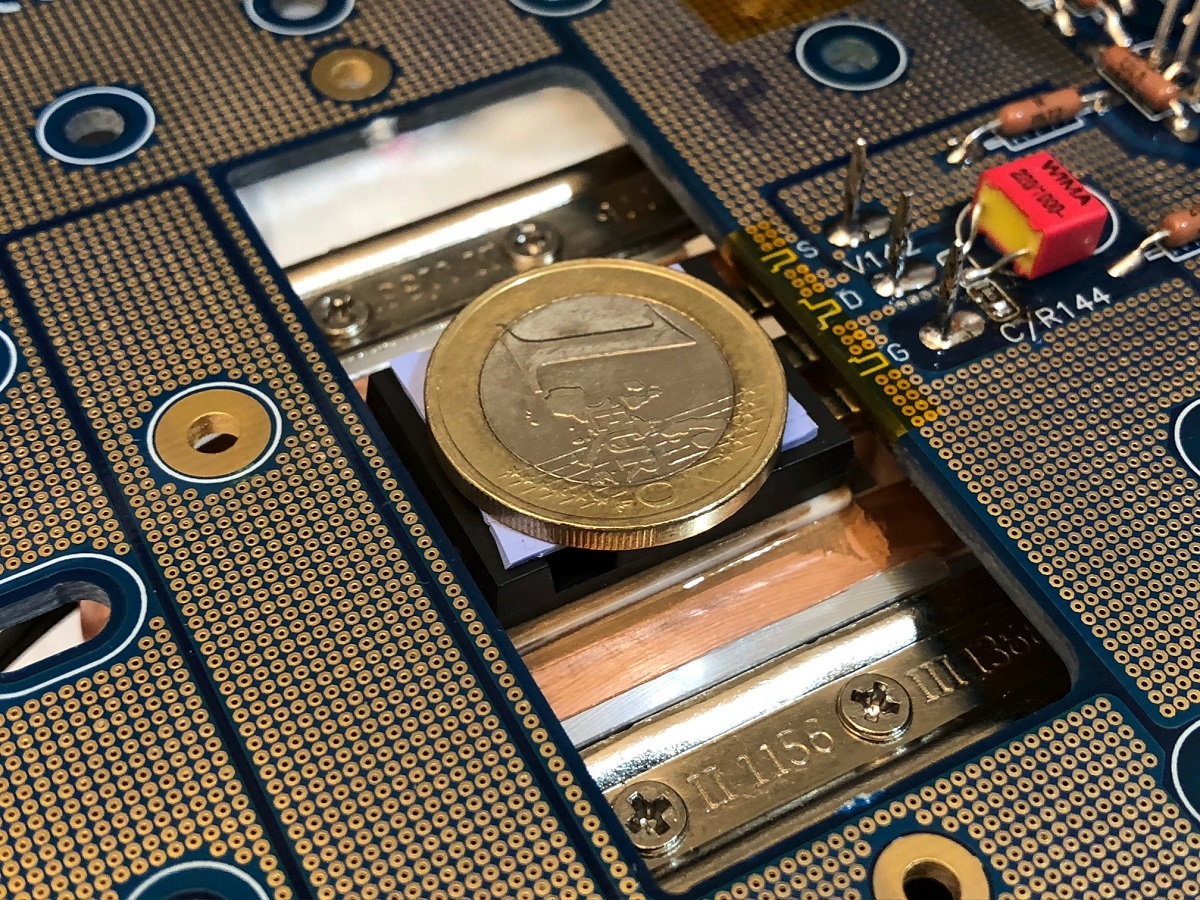
Here is a closeup of the MOSFET on top of the insulator pad and then covered with a blue silicone pad and a thick coin (1 Euro works well) or other spacer:
Here is the Amp singing away on first sound. Firing it up was very uneventful. Current went to 3.00amps rock steady and DC offset is 8mV on this channel. No thump at all. Music is beautiful sounding. The bass authority is exceptional.
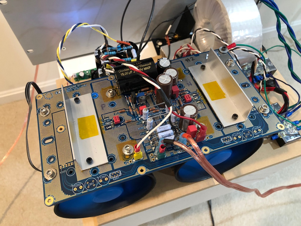
Note above: I am using 2 layers of Kapton tape to insulate the mounting bolts for the CPU cooler from the Drain plane/pour on the top and leaving the 2 bolts near the edge un-insulated because I want them to touch the chassis ground.
Now I need to build a second PSU with CRCRC, trafo, etc. before I can listen in stereo.
The second channel buildup goes so much easier because of lessons learned from the first one. Here are some details of the heatsink with ceramic insulator pad and heatsink compound (gold colored).
Here is a closeup of the paste on the insulator pad on top of the CPU cooler heat transfer surface:
Here is a closeup of the MOSFET on top of the insulator pad and then covered with a blue silicone pad and a thick coin (1 Euro works well) or other spacer:
Here is the Amp singing away on first sound. Firing it up was very uneventful. Current went to 3.00amps rock steady and DC offset is 8mV on this channel. No thump at all. Music is beautiful sounding. The bass authority is exceptional.
Note above: I am using 2 layers of Kapton tape to insulate the mounting bolts for the CPU cooler from the Drain plane/pour on the top and leaving the 2 bolts near the edge un-insulated because I want them to touch the chassis ground.
Now I need to build a second PSU with CRCRC, trafo, etc. before I can listen in stereo.
Attachments


Last edited:
The three of you have done an exceptional job...congratulations!
(With a little help from your friends. 🙂
(With a little help from your friends. 🙂
By the way, the usual recommended method of applying thermal paste by the PC building fraternity is to place a small as possible blob in the centre of the surface. This is because there is little chance of causing trapped air inclusions when the blob is squashed and also avoids a too thick of interface material due to over-application of paste.
The spread approach does work however solid repeatability is only achieved using paste spreading tools which better guarantee the applied thickness and striations
The spread approach does work however solid repeatability is only achieved using paste spreading tools which better guarantee the applied thickness and striations
By the way, the usual recommended method of applying thermal paste by the PC building fraternity is to place a small as possible blob in the centre of the surface. This is because there is little chance of causing trapped air inclusions when the blob is squashed and also avoids a too thick of interface material due to over-application of paste.
The spread approach does work however solid repeatability is only achieved using paste spreading tools which better guarantee the applied thickness and striations
Thanks for the tip. I had to take one apart and repeat the paste application procedure to ensure it was even because I could easily measure that one of the MOSFETs did not have good thermal contact. The IR thermometer on the Kapton patch mounted directly on top of the clamp bar is a great diagnostic. When installed properly, temps register 37-38C. The one that was bad was 50C. After fixing it went down to 37C. I noticed that the CPU cooler came with what looked like a checkered pattern applied presumably via a stencil.

- Home
- Amplifiers
- Solid State
- Aksa Lender P-MOS Hybrid Aleph (ALPHA) Amplifier