Pelatuk OIPC
I have many variation of this topology, and I called it Pelatuk (a bird name) amplifier. Now, I want to change the compensation with OITPC. The goal of this amplifier is cheap enough, use transistors that easily to find in my country, and simple enough.
I have many variation of this topology, and I called it Pelatuk (a bird name) amplifier. Now, I want to change the compensation with OITPC. The goal of this amplifier is cheap enough, use transistors that easily to find in my country, and simple enough.
Attachments
I have many variation of this topology, and I called it Pelatuk (a bird name) amplifier. Now, I want to change the compensation with OITPC. The goal of this amplifier is cheap enough, use transistors that easily to find in my country, and simple enough.
This is PCB layout but not tested.
Please compare with simulation file (sometime I made mistake when convert schematic from simulation file to PCB layout software).
Attachments
I think this amplifier have great potential.
I want less distortion in high frequency. In the latest simulation, I use 2 sets of vertical mosfet with 45VDC PSU. It reduce high frequency distortion slightly and increase the slew rate.
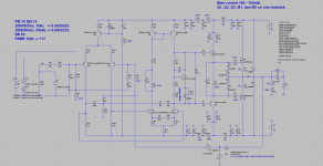
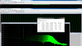
I sim symmetry topology with cascode LTP dan Hawksford cascode VAS, which is very common design ") and output TEF. All BJT. Compensation is OITPC. It is very difficult to implement OITPC using output BJT rather than mosfet. I use 90VDC PSU.
and output TEF. All BJT. Compensation is OITPC. It is very difficult to implement OITPC using output BJT rather than mosfet. I use 90VDC PSU.
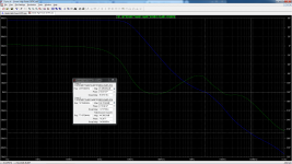
This is loop gain and THD 20.
and output TEF. All BJT. Compensation is OITPC. It is very difficult to implement OITPC using output BJT rather than mosfet. I use 90VDC PSU. This is loop gain and THD 20.
Attachments
I sim symmetry topology with cascode LTP dan Hawksford cascode VAS, which is very common design
This is loop gain and THD 20.
Yes, triple BJT OPS introduces more phase shift (and harder to stabilize)than simple mosfet OPS.

This is PCB layout but not tested.
Please compare with simulation file (sometime I made mistake when convert schematic from simulation file to PCB layout software).
This is Pelatuk OITPC built by my friend.
Attachments
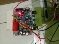
This is Pelatuk OITPC built by my friend.
So how it sound?
So how it sound?
According to my friend, he like the sound, specially the bass (many Indonesia people love the quality of the bass).
I have 4 pcs PCB, given by my other friend, but I have not build it, yet.
Hi Damir, sorry I am a late arriver to this thread.
Is the basic idea of OITPC the following:
1.- Start with regular 2 pole compensation (TPC)
2.- Then, add a capacitor from the T node in the 2 pole compensation to the output to make it OITPC?
Also, in TPC (referring to the schematics in post 1), there is no resistor R22 and R30. What is the purpose of these?
Thanks, Sandro
Hi Bimo, did you ever make measurements of Petaluk?
The simulation post 106 indicates:
- THD @20KHz, ~75Vpp, 8ohm = 0.000464% which is quite low.
Did you get this good results in the actual build?
Best, Sandro
https://www.diyaudio.com/forums/solid-state/338815-anistardi-peletuk-4.html#post5820836
Post 106 is not Pelatuk amplifier.
Last edited:
Hi Damir, sorry I am a late arriver to this thread.
Is the basic idea of OITPC the following:
1.- Start with regular 2 pole compensation (TPC)
2.- Then, add a capacitor from the T node in the 2 pole compensation to the output to make it OITPC?
Also, in TPC (referring to the schematics in post 1), there is no resistor R22 and R30. What is the purpose of these?
Thanks, Sandro
Hi Sandro,
Yes, the basic idea is like that, with some additional tweaking like capacitor parallel to the VAS emitter resistor and added pole to the one TPC leg.
Resistors R22 and R30 (they are actually in parallel) improves, by adding pol, the Phase and Gain margin all at higher frequencies than ULGF (ULGF not changed by this). This pol is used in ordinary TPC or TMC too.
All the best, Damir
Hi Damir,
I went through the fun process today to work out the TPC transfer functions, and yes resistors R22 and R30 add a pole to the network, but a zero to the amplifier to improve phase and gain margin.
Also, the more I stare at OITPC, the technique is an extension of the split Miller cap method. As you correctly pointed out, pure output inclusive Miller is impossible, your amp will go unstable. So you can do 2 things:
- TMC, or,
- Split the Miller cap by feeding some to the amp output and some to the VAS output (op-amps use this technique rather than TMC).
OITPC is an extension of the second one, where the cap that typically goes to the VAS output has been split, and the split portion is now fed to the output. That's how I think about OITPC now that it has sunk in.
Cool technique, simple and gives good results. Thanks for sharing. I
Best, Sandro
Hi Damir, re your question in another thread
- the circuit looks really interesting and I think it is one of the ways how to kill distortion rising with frequency under heavier load. Please let me read the thread more thoroughly.
Hi Pavel,
I would like your opinion about OITPC used by some smart people here in this forum. Cordell did not find a time for that even if he promised to take a look.
OITPC - Output inclusive TPC (not TMC)
- the circuit looks really interesting and I think it is one of the ways how to kill distortion rising with frequency under heavier load. Please let me read the thread more thoroughly.
Hi Damir, re your question in another thread
- the circuit looks really interesting and I think it is one of the ways how to kill distortion rising with frequency under heavier load. Please let me read the thread more thoroughly.
Thanks Pavel, I appreciate your time spent on it.
Best wishes, Damir
Hi Damir,
This is really an excellent design.
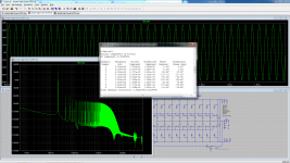
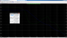
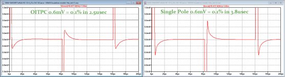
See images below for OITPC and single pole (only 2*250pF from VAS, all other caps removed).
For some reason this .asc file works as expected, while the previous did not ?
As can be seen below, settling time is even shorter with no drama at all, nicely coming to rest as with the Single pole, but then faster.
My compliments for this design.
Hans
This is really an excellent design.
See images below for OITPC and single pole (only 2*250pF from VAS, all other caps removed).
For some reason this .asc file works as expected, while the previous did not ?
As can be seen below, settling time is even shorter with no drama at all, nicely coming to rest as with the Single pole, but then faster.
My compliments for this design.
Hans
Attachments
Hi Damir,
This is really an excellent design.
See images below for OITPC and single pole (only 2*250pF from VAS, all other caps removed).
For some reason this .asc file works as expected, while the previous did not ?
As can be seen below, settling time is even shorter with no drama at all, nicely coming to rest as with the Single pole, but then faster.
My compliments for this design.
Hans
Thank you Hans.
- Status
- This old topic is closed. If you want to reopen this topic, contact a moderator using the "Report Post" button.
- Home
- Amplifiers
- Solid State
- OITPC - Output inclusive TPC (not TMC)