...the cap(s) connected to the VAS output and one part connected to the amp output...
I also started with TPC (TP Input Inclusive in my case) and then added VAS emitter resistor bypass capacitors.
I had a definite reason, the idea that the added capacitors would increase the gain and I could adjust the size of the capacitor to place the gain boost just where I needed it.
I expect your idea was the same, and it works well.
But I did not think to add C8 (or the equivalent in TPIIC), I just wonder what the idea was that you had in mind, just an experiment? or was there some chain of reason, like "this will send feedback from X to Y, so this loop gain will increase/decrease, that loop gain will..."?
Best wishes
David
Last edited:
I also started with TPC (TP Input Inclusive in my case) and then added VAS emitter resistor bypass capacitors.
Have you seen this thread? http://www.diyaudio.com/forums/solid-state/326750-vmos-super-cfa-oiac.html#post5530045
I had a definite reason, the idea that the added capacitors would increase the gain and I could adjust the size of the capacitor to place the gain boost just where I needed it.
I expect your idea was the same, and it works well.
But I did not think to add C8 (or the equivalent in TPIIC), I just wonder what the idea was that you had in mind, just an experiment? or was there some chain of reason, like "this will send feedback from X to Y, so this loop gain will increase/decrease, that loop gain will..."?
Best wishes
David
My idea was to include OPS in the compensation but not as in TMC more in Cherry stile.
I strived for lower OPS distortion, specially crossover type. What surprised me was much better Phase Margin and specially Gain Margin.
Best Wishes, Damir
My experience: during my SA2016 adventures using exicon lateral mosfets I have simulated several variants using a cap/resistor combo from output to tmc / VAS input. Simulation showed better PM/GM margins but testing that in real life circuit the amplifier was unstable till I removed these capacitor/resistor combo ...
BR, Toni
BR, Toni
My experience: during my SA2016 adventures using exicon lateral mosfets I have simulated several variants using a cap/resistor combo from output to tmc / VAS input. Simulation showed better PM/GM margins but testing that in real life circuit the amplifier was unstable till I removed these capacitor/resistor combo ...
BR, Toni
TMC resistor is connected to the amp output. You can put a cap in series with this resistor to remove peaking in the LG, in most cases the cap value is around 100nF. TMC is quite stable, I never had a problem with it.
When you say combo, what it means, parallel or series combination?
BR, Damir
series of course - sorry.
It was C7/R26 - have a look here:
2stageEF high performance class AB power amp / 200W8R / 400W4R
BR, Toni
It was C7/R26 - have a look here:
2stageEF high performance class AB power amp / 200W8R / 400W4R
BR, Toni
series of course - sorry.
It was C7/R26 - have a look here:
2stageEF high performance class AB power amp / 200W8R / 400W4R
BR, Toni
You use TMC as main compensation and then there are options, TPC(R27) and C7 and R26. What compensation was unstable?
BR, Damir
C7/R26 as far as I remember
C7: 10 - 22pF
R26: from 0 - 100R
All possible variants stepped in ltspice and tested afterwards in real life - unstable.
BR, Toni
C7: 10 - 22pF
R26: from 0 - 100R
All possible variants stepped in ltspice and tested afterwards in real life - unstable.
BR, Toni
Have you seen this thread? http://www.diyaudio.com/forums/solid-state/326750-vmos-super-cfa-oiac.html#post5530045
No, I had not, thank you.
I would call this Transitional (Miller) Input Inclusive Compensation.
I compared this to Two Pole IIC and they both can work really well.
I posted the Tian plots and distortion of my VFA version a few years back, I am surprised LKA's distortion is not lower, perhaps some side effect of the CFA.
I will try to have a look and post in that thread if I find an explanation or a fix.
Best wishes
David
Last edited:
A bit of a catch up.
I still don't understand how LTspice determines the phase, looks incorrect.
But I was able to determine the flow thru C8 by a check on the lines in, out and around it.
There is no positive feedback that I can see, so my suspicion was incorrect.
But if it's all one way, and therefore Minimum Phase, why is the phase weird?
I experimented and used just one OP MOSFET - and it worked worse.
Probably the compensation could be readjusted but there was much more effect than I expected.
Maybe it's from the reduced capacitance?
Would explain why you find it easier with MOSFET OP but it's a surprise to me.
A closer examination shows that the "equivalent in TPIIC" probably doesn't do much.
So the fact that I didn't think of it is not so bad😉
But I will check this, just to be sure.
I think I read this back in the early 1970s, when I had many National Semiconductor handbooks.
But I threw them out in early 2010s in a clean up.
Then I rediscovered my interest in audio electronics and was very sorry abut what I had done.
Now you reminded me of my mistake!
But thanks, I appreciate the intention.
Best wishes
David
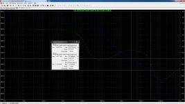
Here is the Tian probe in the C8 capacitor line.
I still don't understand how LTspice determines the phase, looks incorrect.
But I was able to determine the flow thru C8 by a check on the lines in, out and around it.
There is no positive feedback that I can see, so my suspicion was incorrect.
But if it's all one way, and therefore Minimum Phase, why is the phase weird?
I study the compensation. It seems much easier when use mosfet as output...
I experimented and used just one OP MOSFET - and it worked worse.
Probably the compensation could be readjusted but there was much more effect than I expected.
Maybe it's from the reduced capacitance?
Would explain why you find it easier with MOSFET OP but it's a surprise to me.
...But I did not think to add C8 (or the equivalent in TPIIC)...
A closer examination shows that the "equivalent in TPIIC" probably doesn't do much.
So the fact that I didn't think of it is not so bad😉
But I will check this, just to be sure.
...which may be of interest?
I think I read this back in the early 1970s, when I had many National Semiconductor handbooks.
But I threw them out in early 2010s in a clean up.
Then I rediscovered my interest in audio electronics and was very sorry abut what I had done.
Now you reminded me of my mistake!
But thanks, I appreciate the intention.
Best wishes
David
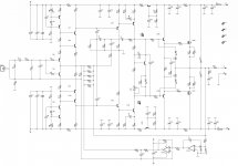
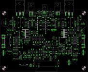
The prototype of my amplifier using this compensation which built by my friend was running stable today. He used un-matching components, DCO was high about 1,8V and then I modified the value of resistor of DC Servo's output. DCO reduced below 1mV. The bias current is over compensated a little bit.
He said the high frequency quality is very good. Monday, I will listening the amplifier.
He said the high frequency quality is very good. Monday, I will listening the amplifier.
The prototype of my amplifier using this compensation which built by my friend was running stable today. He used un-matching components, DCO was high about 1,8V and then I modified the value of resistor of DC Servo's output. DCO reduced below 1mV. The bias current is over compensated a little bit.
He said the high frequency quality is very good. Monday, I will listening the amplifier.
Bimo, when you said "this compensation" do you mean OITPC? Could you show the schematic?
Bimo, when you said "this compensation" do you mean OITPC? Could you show the schematic?
Yes, but I add a resistor series with Cherry's capacitor.
The schematic is not fix yet. I still modify it (through chat with my friend who made the prototype).
Attachments
Yes, but I add a resistor series with Cherry's capacitor.
The schematic is not fix yet. I still modify it (through chat with my friend who made the prototype).
I can see that this amp is very similar to my CFA mosfet. You made this compensation even more complicated, adding not only R29 but R27 and C12 too. Do you have reason for that, could you show the LG plot?
One warning, move output mosfets protection from the drivers bases to the emitters. The protection as it is now is not good enough, I have live experience with it.
The file simulation is at office computer. Sunday, I will find it. But, I have show the Loop Gain in other thread, but I forget what thread 😀
The basic design is same as yours. C9 and C10 are 10nF, just as AC coupling for the compensations, so I can use Silver Mica for C12, C16, and C17. Silver Mica is more expensive than 10nF MKP here.
OK, nice move, but in this case I don't see reason to use R27. It makes additional shunt compensation.
OK, nice move, but in this case I don't see reason to use R27. It makes additional shunt compensation.
R27 is 100K use to get DC zero voltage of the joining point of C9 and C10. Nothing to do with compensation.
I make this amplifier as cheap as possible and use transistors that my friend already have. Some components was given by other friend. So, this is win-win situation. I want to learn this compensation but have no time to build it, and he want a good amplifier.
- Home
- Amplifiers
- Solid State
- OITPC - Output inclusive TPC (not TMC)