Fast linear amps - control amps- use lead-lag compensation . Is that correct? I found that in old script from university where I once attended courses
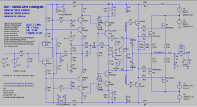
Damir, what about this compensation method ? I'm just before the PCB design is finished. Last chance to change something 🙂 ( I know R30,35 should be replaced by CCS, but improvement is only few ppm)
View attachment 699119
View attachment 699120
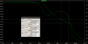
This is similar to TMC, I can't comment just from schematic, and for LG plot better use Tian probe instead, more accurate.
Last edited:
CFA TMIC ? or how to call it ?
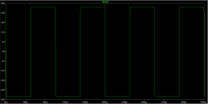
this compensation has better transient response (no sqr wave overshoot), fewer components and the result is very good indeed
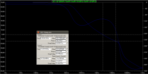
tian probe - it is the same
square wave test - input PULSE(-1 1 0 10n 10n 50u 100u), output 56Vpp@4R
View attachment 699151
View attachment 699152
Leslie, this looks as very good amp with interesting compensation, why don't you open a new thread and attach LTspice file. You would need to add output mosfet protection and could get more suggestion from others.
Probably need to change some BC transistors for higher voltage ones. There better models for output mosfets too.
Damir
why don't you open a new thread and attach LTspice file.
I'll think about it 🙂
All transistors use Cordell models, except Q2,3. Up to +-50V PSU it's safe as it's drawn. D3,4 - flying catch diodes, protect gates from overdrive and also function as natural current limiter. (Cordell book - figure 11.14, page 237/238)
The A1381/C3503 TO-126 combo is good, but the 2sa1381e is VERY hard to find. Is there a replacement for it or them to be had? I am crossing my fingers on some 2sa1381e I bought on Ebay. NONE of the normal GOOD channels have any. Any suggestions? Thanks
you can use 2SA1380E/2SC3502E also
2SC3502 2SA1380 SANYO - Buy Online @ AmpsLab
Yes, they are good too.
I'll think about it 🙂
All transistors use Cordell models, except Q2,3. Up to +-50V PSU it's safe as it's drawn. D3,4 - flying catch diodes, protect gates from overdrive and also function as natural current limiter. (Cordell book - figure 11.14, page 237/238)
Here are IRFP240/9240 models with better subthreshold area:
* VDMOS ksubthres models
*
* IRFP240Ckst VDMOS copyright Cordell Audio December 20, 2014
.model irfp240Ckst VDMOS(nchan Vto=3.0 Kp=4.8 Lambda=0.0032 Rs=0.01 Rd=0.1 Rds=1e7 Cgdmax=2600p Cgdmin=10p a=0.35
+Cgs=1250p Cjo=3000p m=0.75 VJ=2.5 IS=4.0E-06 N=2.4 ksubthres=190m)
*
*
*
* IRFP9240Ckst VDMOS copyright Cordell Audio December 20, 2014
.model irfp9240Ckst VDMOS(pchan Vto=-2.76 Kp=9 Lambda=0.004 Rs=0.064 Rd=0.1 Rds=1e7 Cgdmax=1200p Cgdmin=15p a=0.26
+Cgs=1130p Cjo=2070p m=0.68 VJ=2.5 IS=4.0E-06 N=2.4 ksubthres=107m)
*
Hi
Damir: In post 2 or so you show the phase plot of the amp and it is rippley. Isn't that a problem?
Borys: The 100uF in the ground leg of the feedback loop is too low a value. Yes, Self still shows 220uF in his schematics originally drawn in the 1990s and never updated to his new thinking, but no reason to do it to yourself. Higher vaalues will improve the phase response at low-frequencies and reduce THD even at 1kHz. I use 10mF minimum, but more typically 33mF. (m=milli)
Hi
Damir: In post 2 or so you show the phase plot of the amp and it is rippley. Isn't that a problem?
Could you be more specific, what post?
Hi Damir
Actually, all the plots in post-1 and the ones in post-6, but especially the fourth in post-1.
That ripple in the phase response does not look right to me. other plots I've seen for amps with less sophisticated compensation have smoother phase response. So I wonder is this a fact of the compensation, or more about topology?
I would like to explain my novel compensation
Hi Damir
I wanted to study this more closely since you first posted, and finally made the effort.
I suspect that you have some positive feedback via C8 and C6||C9.
This is not a criticism, I think it may even be beneficial, as below.
Could you put a Tian probe in series with C8 and show the result?
To explain more clearly here is CFA simu[l]ation with enhanced VAS. To remove peak...
I think this peak is not necessarily a problem, theoretically it can be beneficial.
I would be a little careful, of course, hence my interest in the C8 feedback.
Best wishes
David
Actually, all the plots in post-1 and the ones in post-6, but especially the fourth in post-1.
So I wonder is this a fact of the compensation...?
If I may answer for Damir because he is perhaps too modest to explain how nice his implementation is.
The phase response complexity is not just a fact but intentional and beneficial.
This is explained by Bode, the book is now public domain and available on-line.
Best wishes
David
Hi Damir
I wanted to study this more closely since you first posted, and finally made the effort.
I suspect that you have some positive feedback via C8 and C6||C9.
This is not a criticism, I think it may even be beneficial, as below.
Could you put a Tian probe in series with C8 and show the result?
I think this peak is not necessarily a problem, theoretically it can be beneficial.
I would be a little careful, of course, hence my interest in the C8 feedback.
Best wishes
David
Hi David,
I will do that simulation today and come back with the result.
Best regards
Damir
Hi Damir
Actually, all the plots in post-1 and the ones in post-6, but especially the fourth in post-1.
That ripple in the phase response does not look right to me. other plots I've seen for amps with less sophisticated compensation have smoother phase response. So I wonder is this a fact of the compensation, or more about topology?
Hi nauta,
This ripple is a fact of two pole compensation, nothing to do with topology.
Here I use a bit more than simple two pole compensation to enhance it, like splitting output leg and bypassing VAS emitter resistor with suitable capacitor, all that to get better PM and GM wile maintain flat loop gain up to 20 kHz. More detail explanation by Bode.
BR Damir
Thanks David for your help here.
Last edited:
The A1381/C3503 TO-126 combo is good, but the 2sa1381e is VERY hard to find. Is there a replacement for it or them to be had? I am crossing my fingers on some 2sa1381e I bought on Ebay. NONE of the normal GOOD channels have any. Any suggestions? Thanks
2SA1381E replacement is KSA1381E: mouser has > 5000 pcs on stock
BR, Toni
For HF C7/R22 and C14/R30 (from schematic in post 1 and 6) can be seen as paralleled - shorted via C27/C28. I'm sure you can save some parts here if the pcb is carefully designed.
C8: I have tried this variant (cherry?) and the only GM/PM benefit was during simulation. In real life the amps where more prone to oscillation. See discussion with user kgrlee, Dave Zan and others in thread around post +/- 500.
BR, Toni
C8: I have tried this variant (cherry?) and the only GM/PM benefit was during simulation. In real life the amps where more prone to oscillation. See discussion with user kgrlee, Dave Zan and others in thread around post +/- 500.
BR, Toni
Last edited:
2SA1381E replacement is KSA1381E: mouser has > 5000 pcs on stock
BR, Toni
I think that Krisfr meant 2SC3503 and Mouser has D grade only.
- Home
- Amplifiers
- Solid State
- OITPC - Output inclusive TPC (not TMC)


