For HF C7/R22 and C14/R30 (from schematic in post 1 and 6) can be seen as paralleled - shorted via C27/C28. I'm sure you can save some parts here if the pcb is carefully designed.
C8: I have tried this variant (cherry?) and the only GM/PM benefit was during simulation. In real life the amps where more prone to oscillation. See discussion with user kgrlee, Dave Zan and others in thread around post +/- 500.
BR, Toni
I put it lake that intentionally, what are two cheap components (cap could be ceramic NP0 instead more expensive silver mica), and the pcb was carefully designed to keep traces shorter.
I never had problem with oscillation, but then I keep feedback traces as short as possible, and this is different than just cap from output (C8 cherry?).
BR Damir
C8: I have tried this variant (cherry?)...
Hi Toni
I think there is a difference between Damir's OITPC and Cherry.
I was slow to study Damir's scheme because it is hard work to keep the differences clear in my mind (now that I have made the effort I am pleased that I did).
The fact that OITPC and Cherry look similar makes it possible I am confused but I don't recall that we ever tried a circuit quite like Damir's, correct me if I am mistaken.
Best wishes
David
Last edited:
...cap could be ceramic NP0 instead more expensive silver mica...
Audio Precision tests demonstrate NP0 can be better than silver mica anyway.
I also think the balanced layout is a reasonable decision, may help cancel noise pickup or reduce stray capacitance and inductance, at very little cost.
Perhaps I worry too much about symmetry but that is the way I planned to do it myself on a similar circuit.
Best wishes
David
Last edited:
- NP0: agree!
- Thats why I wrote "(cherry?)"😉 - just wanted to say that not all simulated schematic tricks with extra GM/PM results help you stabilize the real amp in real world ...😎
Thats why I wrote "(cherry?)"😉 - just wanted to say that not all simulated schematic tricks...help you stabilize the real amp in real world
OK on Cherry😉
I am not completely sure how close the simulations will be to reality.
I should have mentioned in my reply to Nauta that the phase ripples at hi frequencies are irrelevant because they are so far below unity gain, and anyway the Tian probe is inaccurate when there is non-trivial direct transmission, as there is above 100 MHz.
Not to mention un-modeled stray capacitance, inductance, and transistor non-minimum phase behavior.
But I expect it is accurate at the important frequencies.
And now that I have studied Damir's circuit, I think OITPC has lots of promise.
I had some theoretical ideas about this but Damir has actually built it!
I will definitely have fun to learn if my suspicions are correct (or not) about C8 feed forward.
Best wishes
David
Last edited:
I had some theoretical ideas about this but Damir has actually built it!
I will definitely have fun to learn if my suspicions are correct (or not) about C8 feed forward.
Best wishes
David
Yes David I built some amps with OITPC look here http://www.diyaudio.com/forums/solid-state/317335-oitpc-output-inclusive-tpc-tmc-2.html#post5347908 and Richard Marsh built 200W CFA version in Thailand for him, all working with no stability problems.
BR Damir
Dear Toni,
Simulation can be very accurate, as you know of course, and as Dave said if stray inductances and capacitances are included in the simulation and correspond to the PCB layout (that is hard part, good layout) simulated result is quite close to reality.
BR Damir
Simulation can be very accurate, as you know of course, and as Dave said if stray inductances and capacitances are included in the simulation and correspond to the PCB layout (that is hard part, good layout) simulated result is quite close to reality.
BR Damir
2SA1381E replacement is KSA1381E: mouser has > 5000 pcs on stock
BR, Toni
Yes, I know. I purchased 200 of them. Where to find the KSC3503E is the HUGE problem.
I found some on Ebay and so far when I have checked them they SEEM okay. I just started some electrical testing last night. They are some very good matches HFE wise. I will share the results when I get up to full working voltages. Thanks
I will do that simulation today and come back with the result.
Damir, if you don't have the time to do the simulation then could you post the ASC and I can try it myself?
I don't want to inconvenience you, but at the same time I am very enthusiastic to learn more.
Best wishes
David
Last edited:
Damir, if you don't have the time to do the simulation then could you post the ASC and I can try it myself?
I don't want to inconvenience you, but at the same time I am very enthusiastic to learn more.
Best wishes
David
OK, it's here.
BR Damir
Attachments
OK, it's here.
Thanks, that's better anyway, saves your time and I can experiment.
I need to experiment because I ran a quick first test and I'm not sure what it means yet.
Time to put in one way buffers and try to understand.
Best wishes
David
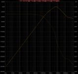
Here is the Tian probe in the C8 capacitor line.
Circuit is the same as Damir's pic. 3 from the first post (1k TPC resistor).
I still don't really understand this, in particular how LTspice calculates the phase.
I have seen this before but always skipped over it, this time I would like to sort it out.
Since the phase is hard to determine I am not even sure if the feedback is +ve or -ve for this loop.
Damir, Toni, Matthias, or anyone have any ideas?
Best wishes
David
Attachments
...
Damir, Toni, Matthias, or anyone have any ideas?
...
Maybe this helps?
HarryDymond answered me a maybe similar probe problem here:
Yes, the position of the probe is correct, but it does not give the loop gain of the inner loop, if the outer loop is active. How can a feedback loop with a capacitor (of order pF) as the feedback element have almost 90 dB of gain at 1 Hz?
See this link:
2stageEF high performance class AB power amp / 200W8R / 400W4R
BR, Toni
David, you know my opinion, outer loop gain will show if there is a problem. I, really can't answer your quest, I am not sure what it shows.
BR Damir
BR Damir
Maybe this helps?...
I will reread that and think more
David, you know my opinion, outer loop gain will show if there is a problem...
Yes, we are in accord, your compensation looks fine.
It's so nice that I want to understand it better, maybe write it up.
I noticed you drew it to the attention of Bob Cordell but I am not sure he appreciated it fully.
It also connects with some other ideas I have had, hopefully I can even find further improvements.
An article would need to have a formula to optimize the values, not everyone can do this with LTspice as well as you have.
Best wishes
David
I study the compensation. It seems much easier when use mosfet as output (may be high capacitance of the gate?). Sometime add resistor series with "cherry" capacitor make it look good in Bode diagram (PM and GM).
Currently I sim a CFA with this compensation with slightly different implementation. Now, a friend make a prototype of it.
Next, I will try symmetry topology (I already sim it).
Currently I sim a CFA with this compensation with slightly different implementation. Now, a friend make a prototype of it.
Next, I will try symmetry topology (I already sim it).
Yes, we are in accord, your compensation looks fine.
It's so nice that I want to understand it better, maybe write it up.
I noticed you drew it to the attention of Bob Cordell but I am not sure he appreciated it fully.
It also connects with some other ideas I have had, hopefully I can even find further improvements.
An article would need to have a formula to optimize the values, not everyone can do this with LTspice as well as you have.
Best wishes
David
I hoped Cordell will take a look and give an answer, but he a did not yet.
David, it will be very nice if you elaborate this compensation and back up it with a formula, I am to lazy and a bit rusty to put an effort. To many other project on go, and that is problem in my age.
Best regards, Damir
I am to[o] lazy and a bit rusty to put an effort. To many other project....
I am a bit rusty in LTSpice too, haven't done any simulations for a while, like you I work on other projects.
But rainy here today, so this is a fine indoor project to make some effort on, and start to remember the skills.
Could I ask you to describe how you see the compensation works?
Sometimes the inventor himself doesn't see it the way I do, like Edmond Stuart and TMC, so I am curious about your perspective.
Best wishes
David
Last edited:
I am a bit rusty in LTSpice too, haven't done any simulations for a while, like you I work on other projects.
But rainy here today, so this is a fine indoor project to make some effort on, and start to remember the skills.
Could I ask you to describe how you see the compensation works?
Sometimes the inventor himself doesn't see it the way I do, like Edmond Stuart and TMC, so I am curious about your perspective.
Best wishes
David
As I tried to explain it in my first post. I started with simple TPC by optimizing it. Than extended the bandwidth by bypassing the VAS emitter resistor with suitable capacitor (this works when the emitter resistor is quite high, in this CFA case 100ohm). The next steps improved Phase Margin and Gain Margin. This was achieved by splitting the cap(s) connected to the VAS output and one part connected to the amp output, and optimizing the TPC resistor value.
All that using Ltspice only. Calculus will simplify this process, but I know from experience some values to start with.
Best wishes, Damir
- Home
- Amplifiers
- Solid State
- OITPC - Output inclusive TPC (not TMC)