Front-end testing
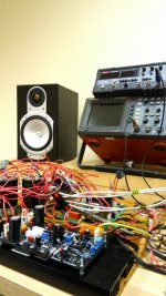
So far so good. Just tested the front-end standalone.
Had to adjust a few resistor values - simulation models showed slightly higher Idss than the real input pair.
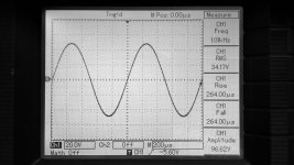
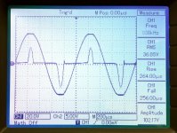
I can't check the spectrums right now (most likely - next week), but what I see on the scope's screen looks promising
So far so good. Just tested the front-end standalone.
Had to adjust a few resistor values - simulation models showed slightly higher Idss than the real input pair.
I can't check the spectrums right now (most likely - next week), but what I see on the scope's screen looks promising
Attachments
Hi Valery,is this the IPS for the NS motherboard or the all in one version(post#95)?So far so good. Just tested the front-end standalone.
Had to adjust a few resistor values - simulation models showed slightly higher Idss than the real input pair.
I can't check the spectrums right now (most likely - next week), but what I see on the scope's screen looks promising
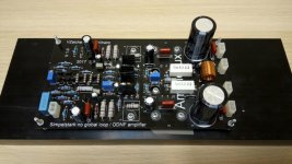
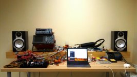
This is the all-in-one version with OPS disconnected.
Working on the heatsink drilling - full scale test is coming soon.
Also, my RTX spectrum analyzer is expected to arrive next week - then we'll see all the details.
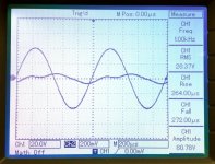
The waves above are performed with no global loop whatsoever - which is pretty cool
Working on the heatsink drilling - full scale test is coming soon.
Also, my RTX spectrum analyzer is expected to arrive next week - then we'll see all the details.
The waves above are performed with no global loop whatsoever - which is pretty cool
This is the all-in-one version with OPS disconnected.
Working on the heatsink drilling - full scale test is coming soon.
Also, my RTX spectrum analyzer is expected to arrive next week - then we'll see all the details.
The waves above are performed with no global loop whatsoever - which is pretty cool
Good news!
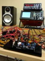
I see that you has assemble your bench again.
Now you will have the opportunity testing farther using a RTX spectrum analyzer!
I wish to have such a thing but i can't afford the high cost.
Very good news!
Last edited:
Yes, version for NS OPS is possible - the all-in-one arrangement I'm working on now will give us some thoughts on how to design it the best way. I've got a lab prototype version of NS-OPS, so that configuration will be tested as well.
Stay tuned - both no-global-loop and ODNF developments look very promising in terms of sound quality
Stay tuned - both no-global-loop and ODNF developments look very promising in terms of sound quality
Initial test of the full all-in-one configuration with no global NFB
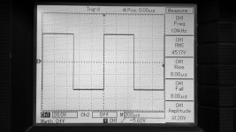
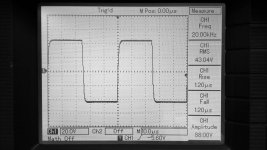
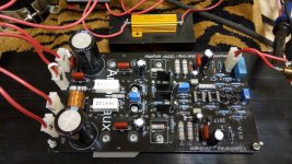
Just finished all the metal works - mounted the board on a heatsink and ran initial tests. Scope pictures are basically the same as shown in post #101 above - now at 8 ohm load, but looking the same. One resistor value in the bias spreader is amended.
Bias is set to 60mA, offset is fluctuating within +/-5mV.
Runs nicely. Rock stable (well, no surprise with no global loop in place)
I made a stupid mistake, re-drawing the schematic in Diptrace (later on it went to the layout accordingly) - first opamp of ODNF circuit has got "+" and "-" inputs exchanged. As a result - I need to arrange some adapter before I can test ODNF mode.
Cheers,
Valery
Just finished all the metal works - mounted the board on a heatsink and ran initial tests. Scope pictures are basically the same as shown in post #101 above - now at 8 ohm load, but looking the same. One resistor value in the bias spreader is amended.
Bias is set to 60mA, offset is fluctuating within +/-5mV.
Runs nicely. Rock stable (well, no surprise with no global loop in place
)I made a stupid mistake, re-drawing the schematic in Diptrace (later on it went to the layout accordingly) - first opamp of ODNF circuit has got "+" and "-" inputs exchanged. As a result - I need to arrange some adapter before I can test ODNF mode.
Cheers,
Valery
Attachments
Valery,
Have you had a good listen? Any thoughts?
Hugh
Hi Hugh!
Not yet - I've got no speakers in my recently rebuilt lab as yet, although I can't wait to audition this amp with some of my "test records". Most likely - early next week. I've got a pair of Monitor Audio RS-1 speakers that I'm going to put in the lab.
Those are not as bass-rich as my RS-8 floor-standers, but very transparent ones at the mids and highs, which is good for the purpose here.
Cheers,
Valery
Neat PCB. I'm about to make some boards made for one of my own circuits. Where did you get yours made?Just finished all the metal works - mounted the board on a heatsink and ran initial tests. Scope pictures are basically the same as shown in post #101 above - now at 8 ohm load, but looking the same. One resistor value in the bias spreader is amended.
Bias is set to 60mA, offset is fluctuating within +/-5mV.
Runs nicely. Rock stable (well, no surprise with no global loop in place
I made a stupid mistake, re-drawing the schematic in Diptrace (later on it went to the layout accordingly) - first opamp of ODNF circuit has got "+" and "-" inputs exchanged. As a result - I need to arrange some adapter before I can test ODNF mode.
Cheers,
Valery
Do you need the output coil?
What is the output stage (I assume you've added one to the schematic in your first post?)
I've counted 20 transistors in the signal path excluding the output stage.
Hi Brian,
The exact schematic of this build is presented in the post #49, including the OPS.
The front-end is much simpler than the one presented in post #1 - that one is much more hi-end one. BTW, I don't consider the big number of active elements as a problem - in many cases, they are required for arranging some "building block" at the appropriate level of quality. For example, in that design in post #1, I use very linear current mirrors, consisting of 4 transistors and 2 diodes in each half of the push-pull structure. 10 parts in total - no problem, it's just a super-linear structure of two current mirrors in push-pull - a single building block.
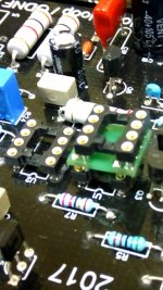
Opamps (ODNF) are not installed yet as I made a stupid mistake and building a small adapter for one of the opamps right now (I hate cutting traces).
The output stage is very simple but rather linear - those lateral FETs make the difference. This simple all-in-one design is a sort of a proof of concept. I've already got a few ideas for rather cool designs based on this one, but providing a higher level of sophistication and linearity
The inductor - I will run some tests, most likely I can easily drop it in a no-global-loop amplifier - just left it in place for being able to test both with and without it.
Cheers,
Valery
P.S. I will update the post #1 soon.
The exact schematic of this build is presented in the post #49, including the OPS.
The front-end is much simpler than the one presented in post #1 - that one is much more hi-end one. BTW, I don't consider the big number of active elements as a problem - in many cases, they are required for arranging some "building block" at the appropriate level of quality. For example, in that design in post #1, I use very linear current mirrors, consisting of 4 transistors and 2 diodes in each half of the push-pull structure. 10 parts in total - no problem, it's just a super-linear structure of two current mirrors in push-pull - a single building block.
Opamps (ODNF) are not installed yet as I made a stupid mistake and building a small adapter for one of the opamps right now (I hate cutting traces
).The output stage is very simple but rather linear - those lateral FETs make the difference. This simple all-in-one design is a sort of a proof of concept. I've already got a few ideas for rather cool designs based on this one, but providing a higher level of sophistication and linearity
The inductor - I will run some tests, most likely I can easily drop it in a no-global-loop amplifier - just left it in place for being able to test both with and without it.
Cheers,
Valery
P.S. I will update the post #1 soon.
My simulations and tests of the front-ends of this kind (no-global-loop) show that significant potential source of distortion would be the input impedance modulation of the OPS.
BJT output transistors, biased properly, form a good follower. However, their base currents change significantly, especially at the collector currents high enough (when driving the load at the high swing), leading to their input impedance modulation strong enough.
So we need a stage in front of them, that will not allow influencing its input impedance by those base currents of the output devices. Laterals are very good at this role. Their input impedance is high enough and constant enough throughout the audio band (input capacitance is low enough and linear enough). I would use some mid-power laterals (TO-220, like 2sk216/2sj79), but those are pretty rare these days. Anyway, even these high-power Renesas devices show good results.
You are right, they are running at around 20mA. My question then - why do you consider gm to be a concern for such a follower configuration?
Cheers,
Valery
I'm not sure whether it should be a concern. I just find it an interesting difference compared with a BJT driver. The FET driver may have a gm of about 40mS at 20mA whereas a BJT would be more like 800mS or 20x higher.You are right, they are running at around 20mA. My question then - why do you consider gm to be a concern for such a follower configuration?
I'm just pointing this out for your consideration.
So far so good
OK - first audition with the "shelf" speakers. Single channel, no global loop mode. Two 6 ohm MA RS-1 speakers in series.
First thing noticed - I like it a lot - it's dead silent at idle. The amp is on, place your ear as close to the speaker as possible - "it's not even silence, it's nothing". No sign of any kind of "hiss" or "hum". Top mark in this domain.
Now - listening to a number of my test records (digital source, 176.4KHz sample rate).
Vocals, acoustic jazz, instrumentally reach "difficult" material like "Impressions of Toledo" and a few Big Band compositions.
Solid sound with neutral tonal balance. Very natural presentation, especially noticeable in the "mids" at highly dynamic fragments. It can easily drive those speakers to SPL, painful for this room, offering very comfortable listening at medium and low volumes - again, demonstrating absolute silence between the tracks.
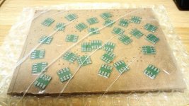
I need to test a stereo configuration with the floorstanders, I'm used to test with, at some point. Also - my small opamp adapter boards have arrived, so ODNF testing is planned for the end of this week. Note, I've ordered 10 boards, but my local manufacturer has sent me 32 of them for the price of 10, as manufacturing process is more convenient that way Jeff, Thimios - some of them will go to you
I also plan to try the beautiful boards, designed by Alex later on - drivers/outputs in one line allow some lower height of the case in general.
Cheers,
Valery
OK - first audition with the "shelf" speakers. Single channel, no global loop mode. Two 6 ohm MA RS-1 speakers in series.
First thing noticed - I like it a lot - it's dead silent at idle. The amp is on, place your ear as close to the speaker as possible - "it's not even silence, it's nothing". No sign of any kind of "hiss" or "hum". Top mark in this domain.
Now - listening to a number of my test records (digital source, 176.4KHz sample rate).
Vocals, acoustic jazz, instrumentally reach "difficult" material like "Impressions of Toledo" and a few Big Band compositions.
Solid sound with neutral tonal balance. Very natural presentation, especially noticeable in the "mids" at highly dynamic fragments. It can easily drive those speakers to SPL, painful for this room, offering very comfortable listening at medium and low volumes - again, demonstrating absolute silence between the tracks.
I need to test a stereo configuration with the floorstanders, I'm used to test with, at some point. Also - my small opamp adapter boards have arrived, so ODNF testing is planned for the end of this week. Note, I've ordered 10 boards, but my local manufacturer has sent me 32 of them for the price of 10, as manufacturing process is more convenient that way
Jeff, Thimios - some of them will go to you I also plan to try the beautiful boards, designed by Alex later on - drivers/outputs in one line allow some lower height of the case in general.
Cheers,
Valery
Attachments
Nice!OK - first audition with the "shelf" speakers. Single channel, no global loop mode. Two 6 ohm MA RS-1 speakers in series.
First thing noticed - I like it a lot - it's dead silent at idle. The amp is on, place your ear as close to the speaker as possible - "it's not even silence, it's nothing". No sign of any kind of "hiss" or "hum". Top mark in this domain.
Now - listening to a number of my test records (digital source, 176.4KHz sample rate).
Vocals, acoustic jazz, instrumentally reach "difficult" material like "Impressions of Toledo" and a few Big Band compositions.
Solid sound with neutral tonal balance. Very natural presentation, especially noticeable in the "mids" at highly dynamic fragments. It can easily drive those speakers to SPL, painful for this room, offering very comfortable listening at medium and low volumes - again, demonstrating absolute silence between the tracks.
I need to test a stereo configuration with the floorstanders, I'm used to test with, at some point. Also - my small opamp adapter boards have arrived, so ODNF testing is planned for the end of this week. Note, I've ordered 10 boards, but my local manufacturer has sent me 32 of them for the price of 10, as manufacturing process is more convenient that way
I also plan to try the beautiful boards, designed by Alex later on - drivers/outputs in one line allow some lower height of the case in general.
Cheers,
Valery
Waiting for this.
ODNF in action!
Thank you High Trying some non-standard things
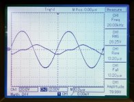
Well - it works! The concept is proved
I have balanced the ODNF subtractor in a way that I see the error signal at its minimum amplitude. This signal modulates the VAS load, correcting the errors, produced by the amplifier (especially the ones produced by the OPS).
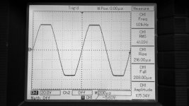
It's easy to see that the error signal at 20KHz is higher than the one at 1KHz - no surprise, just confirming the amp's distortion rises with frequency increase.
It's also cool to see the error signal at clipping - the error correction circuit tries to "pump up" the output swing.
Although ODNF is a global loop, the nature of its application is very different from the "normal" global feedback - ODNF corrects the errors, regardless of where they are originated, but it does not inject the feedback signal to the input. IPS still runs open loop. Neither magnitude nor phase response (open loop) is influenced by ODNF loop - it only corrects the errors, increasing the overall linearity of the amplifier. Correct me if I'm wrong
In terms of the way it sounds - the nature of the amplifier is rather similar. A proper blind A/B test is required - it's very difficult to hear the difference between no-global-loop and ODNF configurations, as the level of distortion seems to be low enough in both cases, although ODNF is called upon to ensure some 20db distortion reduction.
I still can't measure the spectrums, although this is something I'd love to see. Hopefully, my Audio Analyzer is going to reach me soon - looking forward to checking the harmonic profiles and measure THD /IMD.
Hugh, I find the approach very promising. Highly linear stages with fast local feedbacks, plus some overall error correction seems to give a lot of freedom in design approaches without taking too much care about stability
Same silence at idle.
Nice
Cheers,
Valery
Thank you High
Trying some non-standard things Well - it works! The concept is proved
I have balanced the ODNF subtractor in a way that I see the error signal at its minimum amplitude. This signal modulates the VAS load, correcting the errors, produced by the amplifier (especially the ones produced by the OPS).
It's easy to see that the error signal at 20KHz is higher than the one at 1KHz - no surprise, just confirming the amp's distortion rises with frequency increase.
It's also cool to see the error signal at clipping - the error correction circuit tries to "pump up" the output swing.
Although ODNF is a global loop, the nature of its application is very different from the "normal" global feedback - ODNF corrects the errors, regardless of where they are originated, but it does not inject the feedback signal to the input. IPS still runs open loop. Neither magnitude nor phase response (open loop) is influenced by ODNF loop - it only corrects the errors, increasing the overall linearity of the amplifier. Correct me if I'm wrong
In terms of the way it sounds - the nature of the amplifier is rather similar. A proper blind A/B test is required - it's very difficult to hear the difference between no-global-loop and ODNF configurations, as the level of distortion seems to be low enough in both cases, although ODNF is called upon to ensure some 20db distortion reduction.
I still can't measure the spectrums, although this is something I'd love to see. Hopefully, my Audio Analyzer is going to reach me soon - looking forward to checking the harmonic profiles and measure THD /IMD.
Hugh, I find the approach very promising. Highly linear stages with fast local feedbacks, plus some overall error correction seems to give a lot of freedom in design approaches without taking too much care about stability
Same silence at idle.
Nice
Cheers,
Valery
Attachments
- Home
- Amplifiers
- Solid State
- No-global-loop amplification