My circuit has a twin rails power supply. Rload can be connected to ground and its DC function replaced by a Constant Current Source. Does then the CCS belong to the output stage or to the load ? To the load for me, as it is not controlled by the overall negative feedback.You have proven my point. Remove R4 and you don't have an output stage - you don't even have a properly functioning circuit! Therefore, R4 is part of your output stage, which needs a return to V- of some kind to work. And the input stage current clearly flows through that output stage.
Sorry, I have to leave for a few hours. See you later.
Because they do not understand how it work 😉
Btw, my friend finished CFA amplifier with OITPC compensation in stereo. Saturday, we will test how it sound together.
Could you give your listening opinion after, better in the OITPC thread.
Because the industry accepted nomenclature obeys to marketing services and does not necessarily choose the adequate name for a topology.
This statement is wrong and always was. Marketing people are not that smart. I suppose we will be back to some earlier comments that there is no difference at all in any of the amplifier topologies and it was all made up to sell twice as many amplifiers (sort of like MQA).
Could you give your listening opinion after, better in the OITPC thread.
Silk screen held up completion of the CMA. Now it is another 2 weeks until it will be shipped to me.
🙂
THx-RNMarsh
Diverting again from the circuit I recommended:
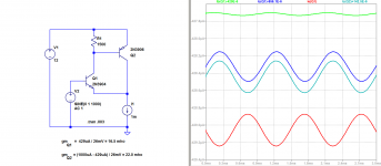
Sure. Add a CCS. Step by step, right? Start with no load, and the simplest possible CFA circuit yet, the first circuit attached. See that the output stage's AC collector current is the input stage's AC emitter current?
Now, if you wish to add a load (AC coupled), you will find that the difference of the load and output stage currents is the input stage current. A combination of the two is fed back into the input stage.
Often the load's and Rg's demands exceed what the input stage alone could possibly provide. But the output stage's current is always in the mix, even when at low signal levels, if Rf were disconnected, the input stage would be capable of supplying all that is necessary to Rg.
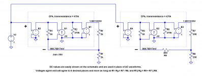
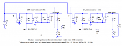
Finally, it is shown (second attachment) that two different non-unity gain feedback networks provide identical performance for two identical CFA's, one of which lacks an "Rg". The CFA works just fine without Rg, and explanations of CFA performance should not depend on its existence, nor of the use of extremely small values for R9.
In a CFA, input stage AC current is a portion of the difference between the load and the output stage AC currents. Whereas in a VFA, that current is in no way a part of that difference. Hence, historicity aside, the technical justification for a description of the operation of the device, and therefore, its name.
Sure. Add a CCS. Step by step, right? Start with no load, and the simplest possible CFA circuit yet, the first circuit attached. See that the output stage's AC collector current is the input stage's AC emitter current?
Now, if you wish to add a load (AC coupled), you will find that the difference of the load and output stage currents is the input stage current. A combination of the two is fed back into the input stage.
Often the load's and Rg's demands exceed what the input stage alone could possibly provide. But the output stage's current is always in the mix, even when at low signal levels, if Rf were disconnected, the input stage would be capable of supplying all that is necessary to Rg.
Finally, it is shown (second attachment) that two different non-unity gain feedback networks provide identical performance for two identical CFA's, one of which lacks an "Rg". The CFA works just fine without Rg, and explanations of CFA performance should not depend on its existence, nor of the use of extremely small values for R9.
In a CFA, input stage AC current is a portion of the difference between the load and the output stage AC currents. Whereas in a VFA, that current is in no way a part of that difference. Hence, historicity aside, the technical justification for a description of the operation of the device, and therefore, its name.
Attachments
What shall we call an amplifier that actually has current feedback then?
Vendors are calling LM3900 a "Quad Single Supply Operational Amplifiers", which I would not being it uses current inputs and can not be used like a normal op-amp. What else would an actual current input be? It would have to be a constant voltage, ie rail or ground referenced.
In a CFA, input stage AC current is a portion of the difference between the load and the output stage AC currents. Whereas in a VFA, that current is in no way a part of that difference.
Correction:
In a CFA, input stage AC current is a portion of some combination of the load and the output stage AC currents. Whereas in a VFA, input stage current is in no way a part of any such combination.
Silk screen held up completion of the CMA. Now it is another 2 weeks until it will be shipped to me.
🙂
THx-RNMarsh
Silk screen on the PCB? Strange.
BR Damir
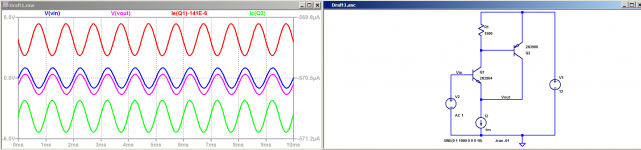
Yes. I didn't go very far tonight. The results with a CCS as the load for the output of the Sziklai pair was a bit deconcerting at first and then very interesting.Sure. Add a CCS. Step by step, right?
I modified my circuit in replaced resistor Rload - 1 kOhm which goes to the negative power supply by a 15 mA CCS. Here are the notes I took :Start with no load, and the simplest possible CFA circuit yet, the first circuit attached. See that the output stage's AC collector current is the input stage's AC emitter current?
Currents in transistors
¨¨¨¨¨¨¨¨¨¨¨¨¨¨¨¨¨¨¨¨¨¨¨
Input T1...............DC...........AC
base......ib1....11,53 µA.....17,01 nA
collector.ic1.....1,15 mA.... 19,83 nA
emitter...ie1.....1,16 mA.....36.84 nA
Output T2
collector.ic2....13.84 mA.....37.02 nA
Comments on the AC values
¨¨¨¨¨¨¨¨¨¨¨¨¨¨¨¨¨¨¨¨¨¨¨¨¨
ic1 is very different from ie1
ic1 is fortuitously about the same value as ib1
ib1 + ic1 = ie, as intended
ic2 = ie1
The two currents converge on the infinite impedance of the CCS which delivers a constant current. If one of these currents increases, the other decreases of the same value, so they have to flow in opposite directions.
The only impedance seen by T1 emitter being the impedance of T2 collector, what is the transconductance of T1 ?
Last edited:
Silk screen on the PCB? Strange.
BR Damir
no. Chassis of course.
-rnm
I modified my circuit in replaced resistor Rload - 1 kOhm which goes to the negative power supply by a 15 mA CCS.
I couldn't quite make out the value of R2 in your circuit to simulate it, so I did the best I could with the first attachment. The sim gives AC currents more or less as I would have expected: ie1 = ic2, and (unlike your results) ie1 is approximately equal to ic1, both of which are a lot greater than ib1. Here, the input stage AC current is the output stage AC current (current feedback).
In the second attachment, two different feedback networks yield identical voltages at the CFA terminals. I have chosen absurd values for R7 and R8 in the circuit on the right to make the point that the inverting input current makes negligible contributions to driving R8. The input current is the difference between the output current and the R8 current. The circuit works just fine without a shunt to ground from the inverting input. (A general explanation of CFA operation must be able to explain this circuit.) Again, we have current feedback.
Attachments
It seems there was something wrong in my yesterday's simulation with ib and ic of T1.For my comfort, I redraw my diagram, the behaviour is now as you say. I changed names of components and values. Power supply is now +/- 10 V. This current in T1 has been adjusted to 1 mA and the CCS current is now 10 mA.I couldn't quite make out the value of R2 in your circuit to simulate it, so I did the best I could with the first attachment. The sim gives AC currents more or less as I would have expected: ie1 = ic2, and (unlike your results) ie1 is approximately equal to ic1, both of which are a lot greater than ib1. Here, the input stage AC current is the output stage AC current (current feedback).
I found ie1 = ic2 in opposite phase when there is no load at the output.
They are in phase when the load is low. So there a must be value of the load where the transition occurs. I found it was about of 382.5 kOhm with curious effects of the shape of the current, the frequency is doubled.
http://iodau.pagesperso-orange.fr/forr_CFA Sziklai CCS.png
More tomorrow I hope.
Last edited:
What are you trying to show or prove?
The notion designates a circuit topology, it does not involve any electrical quantities and any numerical values are irrelevant. There is nothing to simulate.
The notion designates a circuit topology, it does not involve any electrical quantities and any numerical values are irrelevant. There is nothing to simulate.
What are you trying to show or prove?
Not sure to whom this is addressed, but I'll take a whack at it.
Post 812 has three circuits. A Theory of Operation of CFA's should be sufficiently general to cover all three. A simple one that does is that CFA input stage current is not simply equal to, but actually is, some combination of output stage and other currents (current feedback). This is one way to distinguish CFAs from VFAs, for which this is not true.
There are those who prefer to look at CFAs in other ways, which may also be valid (although I am unaware of a method that applies to all three circuits.) It is possible to explain a phenomenon in more than one way. However, we should always keep Occam's Razor in mind.
The problem occurs with the outright rejection of some of the explanation of current feedback.
It seems there was something wrong in my yesterday's simulation with ib and ic of T1.
I am happy to grant that with any significant load, the input and output stage currents are in phase. With no load, they are out of phase, and the CFA employs positive current feedback!
Looking at things from your point of view, two sources (input and output stages) feed a common, source-less network. There is a simple relationship between the currents from these sources: the input stage current is (is not simply equal to) the ground current from the feedback network and load minus the output stage current. The current feedback is now negative from the output, and includes a contribution from the network/load current (almost all of which comes from the output stage anyway.)
This simple statement applies to all three circuits of post 812. Do you have a similarly simple alternative that covers them all?
This statement cannot be applied to a VFA. Its different operation leads to some inherently different characteristics (although some clever designers have introduced moderately complex enhancements to VFAs which narrow some of this gap.)
Finally, here is for me another instance of deriving a deeper understanding from having to defend a point of view. Thank you for your contribution to the insight that current feedback in a load-less CFA is positive!
Last edited:
CFA vs VFA
In my opinion if you are going to compare a CFA versus VFA circuit you should use the same “building blocks” (not a Diamond vs a LTP) You can of course use a LTP (VFA) compared to a single transistor (CFA) IPS with the FB node connected to the E of the IPS BJT (You can of course use FET’s if you prefer).
If you are using a diamond in a CFA you should use a diamond to buffer the feedback node by another diamond in a VFA making an H-bridge.
It should be very easy to see that in a CFA you are using an error current directly to manipulate “Correct” the IPS collector signal current so that you have a current out of the input stage that will reproduce the input voltage signal as good as possible at the output (Voltage) of the amplifier.
In a VFA you are using a divider to make a signal voltage at the input of the second diamond to create the error current that you present to the first diamond.
Remember that whatever input stage you are using you have a standing current modulated by a signal current (and an error current if you use NFB).
Calling it a “Current Mode Amplifier” as RNM and Bonsai prefer is in my opinion meaningless nonsense.
In my opinion “Current Mode” includes an open collector.
I see that R.N Marsh says that he published (invented) the CFA circuit in the 1970’s.
The first modern solid state CFA that I know of was designed in 1967 by Harry Robert Eckes in his thesis of dissertation (page 36) He says that it is an outgrowth of a circuit suggested by D. J. Hamilton in 1964.
Actually he just added an emitter-follower output stage.
(D.J. Hamilton was a well-known author of a lot of documents regarding solid state and integrated circuits)
I guess Walt J and Scott W have read some of his work.
Cheers
Reodor
Adding a emitter follower or a feedback signal to an emitter or to a tube's cathode etc... does not in itself cause the characteristics of a CMA as we know of today.
See #1540 in the Marsh Headphone Amp here in DIYaudio. It is a copy of Linear Audio on the design and origins.
THx-RNMarsh
Last edited:
c
Calling it a “Current Mode Amplifier” as RNM and Bonsai prefer is in my opinion meaningless nonsense.
Reodor
I am staying with the IEEE designation for this type of amplifier .
-RNM
Adding a emitter follower or a feedback signal to an emitter or to a tube's cathode etc... does not in itself cause the characteristics of a CMA as we know of today.
See #1540 in the Marsh Headphone Amp here in DIYaudio. It is a copy of Linear Audio on the design and origins.
THx-RNMarsh
You clearly don’t understand what I'm writing or you deliberately choose to misunderstand.
R
- Home
- Amplifiers
- Solid State
- Current Feedback Amplifiers, not only a semantic problem?