Your spread of tolerance is too great on your ouputs devices with .5 ohm emmiters
If you purchased these from the same lot, a 10% spread would be an acceptable
tolerance
Hi AVWERK yes I got them all from rs components
Turn the bias down, power one amp at a time, find the faulty one (both?)
Let us know what you find, or just ask more questions.
Hi Itsmee! Thanks for your comments. I use SMPS double rails for each channel ie completely individual PSU's. They are made especially for audio and include EMI filtering, soft start and auxiliary +-12V. Should I filter the power cables maybe?
I blew the power mosfets STF21NM50N and plan to replace with FDPF18N50. Is this a good choice? What more can be damaged?
I will use the lab PSU and start without the power transistors. What shall I look for? How do I turn down the bias current in advance?
I plan replace the power transistors from MJL4302/4281 to MJL21293/21194 as original. Any thoughts about that?
I have bought parts mostly from respected sources however these pcb's not...
I will start (read&measure)*n algorithm now and will update as I make progress/holy smoke

KSA-50 double cloned crash
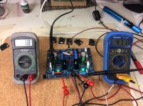
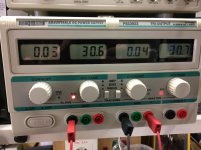
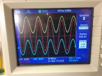
Reading and measuring the pcb with drivers only. The output signal is taken at R127 and R128. DC of set is less than 1 mV at +-30V supply. Clipping start at 1.3Vrms. The red curve of the oscilloscope is the sum of each side. The temperature of the MJE15032/15033 reads less than 55C without zink so I guess I am on track?
Reading and measuring the pcb with drivers only. The output signal is taken at R127 and R128. DC of set is less than 1 mV at +-30V supply. Clipping start at 1.3Vrms. The red curve of the oscilloscope is the sum of each side. The temperature of the MJE15032/15033 reads less than 55C without zink so I guess I am on track?
Attachments
I looked before I posted, you beat me to it again 
Is this the SMPS? Good luck, I avoid them like the plague.
STMicroelectronics recomended replacement for STF21NM50N is SPA21N50C3.
Smoke - you don't want any.
If you don't have the output connected, no need to worry about the bias; the transistor in the circle between the 15034 & 15035 is the bias transistor (15034?), the preset resistor connected to the base adjusts the bias voltage (Google 'amplified diode'), set to minimum voltage before connecting the output stage.
I blew the power mosfets STF21NM50N and plan to replace with FDPF18N50. Is this a good choice? What more can be damaged?
Is this the SMPS? Good luck, I avoid them like the plague.
STMicroelectronics recomended replacement for STF21NM50N is SPA21N50C3.
I will use the lab PSU and start without the power transistors. What shall I look for? How do I turn down the bias current in advance?
Smoke - you don't want any.
If you don't have the output connected, no need to worry about the bias; the transistor in the circle between the 15034 & 15035 is the bias transistor (15034?), the preset resistor connected to the base adjusts the bias voltage (Google 'amplified diode'), set to minimum voltage before connecting the output stage.
Go for it - if you can find genuine parts.I plan replace the power transistors from MJL4302/4281 to MJL21293/21194 as original. Any thoughts about that?
Last edited:
Thinking about it, jacco has some genuine Toshiba 2SA1302 & 2SC3281, they might be a nice alternative for the output.
FS various semiconductors and opamps
FS various semiconductors and opamps
Reading and measuring the pcb with drivers only. The output signal is taken at R127 and R128. DC of set is less than 1 mV at +-30V supply. Clipping start at 1.3Vrms. The red curve of the oscilloscope is the sum of each side. The temperature of the MJE15032/15033 reads less than 55C without zink so I guess I am on track?
Hi Lejonkungen,
I have the same board as you did, and I have been enjoying it for 3 years.
I have purchase all parts from RS and built it slowly for almost 1 year.
Sometimes you may think it was an oven when you turn it on for some time. (+85C...)
Enjoy your DIY time!
An externally hosted image should be here but it was not working when we last tested it.
An externally hosted image should be here but it was not working when we last tested it.
Thinking about it, jacco has some genuine Toshiba 2SA1302 & 2SC3281, they might be a nice alternative for the output.
Thanks Itsmee, I had a look at the link. I'm not so familiar with the transistor world, are Toshiba superior in a specific way?
Hi Lejonkungen,
I have the same board as you did, and I have been enjoying it for 3 years.
I have purchase all parts from RS and built it slowly for almost 1 year.
Sometimes you may think it was an oven when you turn it on for some time. (+85C...)
Enjoy your DIY time!
Thanks for your info and pics of an impressive and compact clone
. I have not found anyone until now using this pcb that I find very well designed. I just got a bad sample with the power-fets on their wrong place.
As I get on I hope I can ask you some questions about your experience.
As I get on I hope I can ask you some questions about your experience.
 I'm curious about your design. Could you share some information about your clone, what kind of set up and modules you have used? Also some basic specs from PSU.
Transformer: A 1200w R-core with 38vac;
Modules: MJL21193/4.
I am not sure if you got the instructions from the seller, but here are some key points:-
- Multimeter on TP1 and TP2: Tune the pot at R105 to the closest of 0-3mV;
- Multimeter on TP2 and TP3-8 for the transistor: Switch on the power for 30 mins, then fine tune the pot at R126 by using ohm's law: i=u/r to the sweetest spot you feel comfortable, ,maintain the temperature within 70-80C are fine enough.
Happy building!
Perfect, thanks!
Thanks Itsmee, I had a look at the link. I'm not so familiar with the transistor world, are Toshiba superior in a specific way?
Toshiba use to make some very nice transistors for audio, the JFETs are highly sought after.
Toshiba use to make some very nice transistors for audio, the JFETs are highly sought after.
Ok, I will give it a try.
Another question. When I set the DC to zero on the output i assume I shorten the input? Is this the same procedure for measuring the bias current on the power transistors?
Yes, you don't want any noise to modulate the output.
That's what I thought. What about connected load/speakers on the final output?
Wow, I see this thread is still going after 15 years!
I wanted to build a clone, then came across the majority of the hardware, original case, transformers, heatsink assembly etc, but no driver board, psu. I've had the parts almost 10 years now and still haven't got back to building it yet.
I wanted to build a clone, then came across the majority of the hardware, original case, transformers, heatsink assembly etc, but no driver board, psu. I've had the parts almost 10 years now and still haven't got back to building it yet.
Wow, I see this thread is still going after 15 years!
I wanted to build a clone, then came across the majority of the hardware, original case, transformers, heatsink assembly etc, but no driver board, psu. I've had the parts almost 10 years now and still haven't got back to building it yet.
Snap, well almost. I built a KSA clone many years ago using Jan's PCB's de-rated to 25W so I could use passive cooling, still working fine. Over time I have gathered most of the parts to construct a higher power version using forced air cooling. Maybe not the most technically advanced amplifier, but still good to listen to and fun to build, a great project for the long winter nights ahead plus it will help keep me warm.
Regards
Alan
- Home
- Amplifiers
- Solid State
- Krell KSA 50 PCB