What is your supply voltage, quiescent current and speaker impedance? Was U / 2 checked at the exit? Twisted pair (screen) at the input? Pinout KTC1845? NPN or PNP 1015?
Replace the TYP41c driver?
Supply is 24V single ended. Bias current was 1.0A, then 1.2A and then 1.5A. Did not affect the undesirable mid & high distortion or "slightly plugged ear"-like sound. (But did improve other aspects of the sound.) Output mid-point voltage is ok.
Test bench speakers are Polk CS1 which claim to be 8 Ohm but I had read online some thoughts that the CS1 and R50 are more like 4 Ohm but I don't know. I have a higher current 24V supply in progress to further explore the possibility that I need more current due to lower than claimed impedance.
Polk Audio CS1 (Black) Center channel speaker at CrutchfieldAnchor a high-impact Polk Monitor home theater speaker system with the CS1 center speaker. It features dual 5-1/4" Dynamic Balance® woofers and a 1" Dynamic Balance dome tweeter. The woofer cones are stiff and lightweight for rich sound and low distortion. They really excel in the midrange — an absolute must for reproducing clear on-screen dialogue. The non-resonant MDF construction ensures cleaner, more lifelike sound.
Correction: I bought pairs of KTC1845 and KSA992. I put KSA992 instead of 2SA1015 as input and TTC004 as driver. Left channel is D1047 outputs from LJM kit and the right channel is TIP35C outputs from authorized distributor.
The undesirable mid & high distortion and "slightly plugged ear"-like sound was present in the original as-shipped state and was not changed as I made each transistor and capacitor (and bias) change. [But those changes did improve other aspects of the sound.] Only when I made the last change did I get a big improvement (the last changing involving removing all output caps, adding the inductor and 10 Ohm "jumper" and then putting back only the 10,000 uF 50V Nover and 0.47 uF MKP as output cap external to the board).
The input is wired from a small Alps RK27 adapter board to the mini1969 via short (couple inch) jumpers. I could twist those short jumper wires.
Last edited:
I hate to say it, but this is where a 'scope shines and you could then probably identify what type of misbehaviour the amplifiers are actually up to. To attempt some answers, the coil/resistor combo is unlikely to cause problems but I wouldn't use it when there is already a massive output cap. in series, as that forms a likely nasty (even if damped) resonant circuit.
Well sometime in the future I would like to add a nice scope to my bench. I have built a couple of (lower speed) scopes with various size LCD color screens. Perhaps I can do something with a 1 kHz input square wave when I get more time for more extended experiments.
But now that the output capacitors are wired externally it is a quick experiment to short the output inductor and resistor with a quick jumper on the bottom of the board. I can easily try that.
Though I'm not clear on what parts you have to work with, I'd revert to original condition and retest each module to be certain whether they both have the same problem. Then you'll know whether it's a parts quality/design problem or its an error, bad part, soldering etc. Replacing the TTC004 with something slower would be a better way to check for oscillation if you have no direct means of checking it. Maybe BD139 or even 2N5551 would be ok to use for a brief test at low output level.
I have genuine 2N5551 but no BD139. I am thinking of ordering more of these mini1969 boards to continue my experiments. That would be easier than reverting these boards. I don't think they will stand up to reverting everything. I don't think the copper or especially the thru hole plating is thick enough. They held up ok for being so inexpensive however when I removed the input 2SA1015 one the boards really came apart with two lifted traces so I installed the KSA992 on the back. For all of the capacitor and larger transistor modifications the boards held up well enough.
Last edited:
You may have problems with oscillation which the inductor and resistor may have helped to suppress. I could imagine that oscillation is more likely with the D1047 but not the TIP35's as the fT's are around 30MHz and 3MHz respectively. The JLH was stable with 4MHz MJ480's originally. As I've reported, there are mixed results when high frequency devices are used.
Other things which can cause oscillations are longish power leads, improper earthing and/or screening which allows input signals to get picked up from the output.
From the images it appears there are capacitors across the power rails - is this right? even with 3-4MHz devices, lead lengths to the main smoothing capacitor need to be short, but if not, additional capacitors connected as long as they are grounded properly.
I take it you have a common earth point and screened input leads?
I've not known an output inductor cause oscillations, and only ringing when a capacitive load is placed on the amplifier. But they are usually accompanied with an RC series pair across the output of the amplifiers too, before the LR pair. This is to keep the impedance low at high frequencies (10 ohms, 47nF typical). Just adding an inductor may keep the load impedance high which increases open loop gain, and hence possible sensitivity to oscillations. If that is the cause, which , as Ian also points out, really only a scope will reveal what is going on.
Other things which can cause oscillations are longish power leads, improper earthing and/or screening which allows input signals to get picked up from the output.
From the images it appears there are capacitors across the power rails - is this right? even with 3-4MHz devices, lead lengths to the main smoothing capacitor need to be short, but if not, additional capacitors connected as long as they are grounded properly.
I take it you have a common earth point and screened input leads?
I soldered a 12,000 uF 35V Nichicon directly to the leads of the output transistors using as short as possible 16 AWG jumpers. I did that since the mini1969 boards have no Vcc caps at all. I then soldered the power supply connector, inrush NTC and current/bias sense resistor to the terminals of that snap-in Nichicon. The capacitor value was just what I had on hand.
Each amplifier has a common earth point and each amplifier runs on an independent power supply. The boards are very small and the trace is reasonably wide and short.
The input leads are screened up to the small Alps RK27 adapter board then short (couple inch) jumpers run from the RK27 adapter board to each mini1969. I could screen or twist those short couple inch jumpers. That is a temporary installation while experimenting on the bench. When I finalize an amplifier I wire it internally with Rapco Horizon MIC2.K cable.
Last edited:
I've not known an output inductor cause oscillations, and only ringing when a capacitive load is placed on the amplifier. But they are usually accompanied with an RC series pair across the output of the amplifiers too, before the LR pair. This is to keep the impedance low at high frequencies (10 ohms, 47nF typical). Just adding an inductor may keep the load impedance high which increases open loop gain, and hence possible sensitivity to oscillations. If that is the cause, which , as Ian also points out, really only a scope will reveal what is going on.
These mini1969 boards have none of those components as shipped. I could add the RC series pair. Perhaps I can try an experiment where I short the inductor on the bottom of the board (to see if it goes back to being worse) and then I can remove that short and add an RC series pair as a next experiment.
PCB mini1969 has two-way wiring.
The holes (caps) go right through and pass to the other side!
https://aliexpress.ru/item/32606225...11.396425444.1602086932-1010815310.1602086932
https://aliexpress.ru/item/32815377...05.396425444.1602086932-1010815310.1602086932
https://aliexpress.ru/item/32810070...25.396425444.1602086932-1010815310.1602086932
https://aliexpress.ru/item/40013026...05.396425444.1602086932-1010815310.1602086932
Yes but the pads and traces come off fairly easily.
I have found that when the copper (especially the thru hole copper plating) is thin the boards are more fragile.
They were not bad for the price but the smaller pads for the 2SA1015 came right off one board the first time I reworked that area.
I have found that when the copper (especially the thru hole copper plating) is thin the boards are more fragile.
They were not bad for the price but the smaller pads for the 2SA1015 came right off one board the first time I reworked that area.
Not good. I'm surprised at such poor bonding of the copper since those boards, kits and assemblies are now selling at premium prices (relative to other Chinese modules and kits). I have a pair in transit as I thought this would be a good way to compare apples etc. but long delays for fumigation or shuffling goods to secondary holding depots, now keeps us waiting on deliveries for months 🙁
The larger components (outputs, driver, caps) were no problem to rework.
But be careful with the input transistor (2SA1015). One board was ok but the other had two lifted pads just removing the 2SA1015.
The only reason I replaced it is because I can't trust that any transistor on these boards are what they say they are. So I would rather just put in the KSA992 which I had.
Do not remove the parts, but bite off the leads and leave the pin.
Short circuit the input and output capacitors with a jumper. Install outside PCB.
Zobel on the outlet connector.
Short circuit the input and output capacitors with a jumper. Install outside PCB.
Zobel on the outlet connector.
Last edited:
How have you been removing the parts? If heating with an iron and pulling, that does tend to pull the tracks at times. That's happened on some of my home-made PCB's.
I've also snipped the leads as OldDIY suggests, but that leaves wires which can flop around next time they see the iron. If you use desolder braid that sucks up the solder and if done properly, the parts just fall out or only need a minimum of assistance.
Be careful with solder wicks. Some have resins which give off harmful vapours and should only be used with a fume filter/extractor.
Yes I should have done that for the input transistor.Do not remove the parts, but bite off the leads and leave the pin.
That works well because of the size of these boards. The boards are too small for the capacitor types and sizes needed.Short circuit the input and output capacitors with a jumper. Install outside PCB.
Zobel on the outlet connector.
How have you been removing the parts? If heating with an iron and pulling, that does tend to pull the tracks at times. That's happened on some of my home-made PCB's.
I've also snipped the leads as OldDIY suggests, but that leaves wires which can flop around next time they see the iron. If you use desolder braid that sucks up the solder and if done properly, the parts just fall out or only need a minimum of assistance.
Be careful with solder wicks. Some have resins which give off harmful vapours and should only be used with a fume filter/extractor.
Sometimes I add fresh solder and then wiggle a two leg component (such as a cap) out. Other times I add fresh solder and the use desoldering braid.
I find that first adding some fresh solder and flux helps.
I used a combination of both on these boards. But with the input transistor adding fresh solder and wiggling just lifted the traces.
Last edited:
Though I'm not clear on what parts you have to work with, I'd revert to original condition and retest each module to be certain whether they both have the same problem. Then you'll know whether it's a parts quality/design problem or its an error, bad part, soldering etc. Replacing the TTC004 with something slower would be a better way to check for oscillation if you have no direct means of checking it. Maybe BD139 or even 2N5551 would be ok to use for a brief test at low output level.
I did a quick experiment last night and soldered a short jumper across the output inductor. That degraded the sound quality noticably but it did not become quite as bad as when the original output capacitor was installed along with the added output capacitors in parallel with that original/factory installed output capacitor.
I then removed the short and added a Zobel RC on the board and the sound quality returned to the improved state. (Or maybe just slightly better.)
So I suspect that adding the inductor (with parallel 10 Ohm) on the output is responsible for some of the improvement. But I wonder if removing the original "Chang" output capacitor could possibly be responsible for part of the improvement?
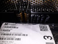
I next removed the two 220 uF 35 V "Chang" capacitors and replaced them with 220 uF 50V Nichicon Muse capacitors that I had left over from upgrading the power amplifier capacitors inside my Denon AVR-3805.
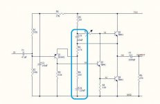
Now the sound quality has improved again. The unpleasant mid/high distortion and the "slightly plugged ear or mild cold" characteristic is gone now. I have marked the two 220 uF capacitors on the attached schematic. Are these considered critical components in the JLH? Replacing those made a big difference. (One of the clearest examples I have found of capacitor quality making an audible difference.) I have attached photos. The original capacitors are very tiny compared with the Nichicons.
What are your experiences with these two 220 uF caps? What has worked best in that location? (Capacitance, brand and series?) What brand, size and type are used there in a "high end" JLH?
Attachments
Last edited:
I've lost track of what transistors you are actually using now. Your diagram shows TIP41's as both driver and output. They have two time constants about the same, and that combination does not need much of an additional phase shift to oscillate or at best have some overshoot in the response (marginally stable).
You should use a fast transistor for the driver stage similar to the BD139 if you do not have that one. With two fast stages, the output stage provides the roll off needed for stability.
With three fast stages there is opportunity for oscillation, which is why I suggest a compensation capacitor should be used, but it could be that differences in Cjc may explain why some builders do not seem to need it. Not looked into that in any detail. (add to the lengthening list of "things to do sometime"?)
Input is KSA992 from authorized distributor.
Driver is TTC004 from authorized distributor.
Left channel outputs are D1047 from LJM kit.
Right channel outputs are TIP35C (ST) from authorized distributor.
Driver is TTC004 from authorized distributor.
Left channel outputs are D1047 from LJM kit.
Right channel outputs are TIP35C (ST) from authorized distributor.
With three fast stages there is opportunity for oscillation, which is why I suggest a compensation capacitor should be used, but it could be that differences in Cjc may explain why some builders do not seem to need it.
What compensation capacitor values have you used and with what transistors types?
Are you adding a capacitor to the driver (BC) for compensation?
Last edited:
Thanks for the reminder. For simulation, the KSA992 seems similar to the BC556, and the TTC004 not too different from the BD139. There may be small differences in capacitances, and they will affect the results, but broadly the BC556 is a lowish noise, high frequency small signal device, and the BD139 is a medium power 100MHz-ish device.
I've used a 33pF across the feedback resistor, not BC "Miller" connection. Though for slightly better stability it maybe should be connected between the collector of the driver and emitter of the PNP. The Miller connection is of course a widely used solution as it is robust, but I prefer not to use it unless the input stage is degenerated enough not to overload (as Cherry did) or has a high enough current to be able to drive the capacitor at high frequencies (like Stochino's design).
Just another quick thought - is your input path a high impedance?
The stability depends on the frequency response of each stage, and if the input sees a high impedance, that lowers its response which will increase the phase shifts into the same region as the driver/output devices (with a fast output stage).
That could be only 1k for example, which will depend on your preamp/input wiring.
If higher than about 100 ohms it may be worth a small capacitor from the PNP base to ground (47-100pF). It's not an input filter as such (though it will filter high frequencies, depending on your source impedance etc), but keeps the input impedance low. You may also need a series resistor and for high frequency response, something in the region of the proverbial 50 ohms (a common RF impedance) works.
Well my test bench signal source consists of a Sony CDP-CA70ES but then an Alps RK27 50k potentiometer before the amplifiers. The RK27 wiper is typically around 5k Ohms.
I do not have a buffer after the Alps RK27. Is this is a mistake with a JLH?
I am not using a pre-amplifier or buffer before the amplifier. Should I try to make a simple discrete Class A JFET buffer?
Last edited:
Try a 100pF capacitor across the input first. If that solves the problem, I'd expore smaller values.
If that works but you loose treble you could add a JFET buffer but that might increase distortion. Might be OK with a PNP gain enhancement (wired like a CFP stage) and/or a constant current source to minimise current variation.
If that works but you loose treble you could add a JFET buffer but that might increase distortion. Might be OK with a PNP gain enhancement (wired like a CFP stage) and/or a constant current source to minimise current variation.
- Home
- Amplifiers
- Solid State
- JLH 10 Watt class A amplifier