Thanks for sharing this with us Nigel!
Which results can be expected with a classic capacitance multiplier on a transistor?
Also, what is the benefit of using large capacitor can after SMPS, e.g. 10mF? I have an oscilloscope and I see in my SMPS the main issue is high frequency ripple. To filter that one might need a 100-500uH choke or even two of those with X-caps of about 10uF. I could not see any difference in ripple between 10uF and 2200uf used after chokes.
Last edited:
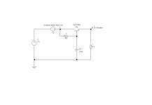
Here is a circuit you could use to represent a power supply with noise. You can set the AC to any frequency and amplitude of course.
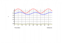
The second picture shows the effect of no filter, a 0.05 ohm resistor and 100uF capacitor, and an active filter as indicated. Note the voltage drop, which is unavoidable.
The simulated peak to peak ripple voltages are 400mV, 288mV and 28mV. The transistor has increased the apparent capacitance by 10x - actually, the base voltage has a lower ripple due to the use of a higher base resistor.
If a choke does not help that is an indication your ripple is getting into your scope by another mechanism - perhaps the earthing arrangements. An LC filter should always be better than an RC filter as it creates a -12dB/octave cut off instead of -6dB/octave with an RC filter. Provided the choke is designed for the frequency it is suppressing. Parasitic winding capacitances can let through very high frequency signals. If the (ferrite or iron) core saturates it won't behave as a choke. Or if the frequency is too high the ferrite core will absorb too much power and still not perform well.
Attachments
NOthing to do with the JLH, but I built a digital clock many years ago. Used two circuit boards stacked, with one having battery backup for the timekeeping. It had a standard common mode filter on the mains input. Very disappointed on first testing! Every time you switched the mains on and off it would read a different time, despite the battery changeover working well.
My cure was to add a current compensated common mode choke (hand wound using a pot or RM core, can't quite recall) on the 5V supply lines. After that it was rock solid. As many times as you wanted to switch on and off. Which was just as well as it had also got an alarm time function.
I don't think that idea would work for a stereo system unless everything can be kept to the filter side of the CMC. Preamps/CD decks etc needing earthing could bypass the CMC and spoil its actions.
Thanks for sharing this with us Nigel!
Which results can be expected with a classic capacitance multiplier on a transistor?
Also, what is the benefit of using large capacitor can after SMPS, e.g. 10mF? I have an oscilloscope and I see in my SMPS the main issue is high frequency ripple. To filter that one might need a 100-500uH choke or even two of those with X-caps of about 10uF. I could not see any difference in ripple between 10uF and 2200uf used after chokes.
As you can see I managed - 111 dBV noise with ripple some 6 dB worse at 1.5 amps. I suspect a capacitance multiplier can better that. The ripple would be tougher.
I learn with every smps I test. If I can find others I will show them.
PNP Version is TR1 still highest gain?
I have a Chinese PNP version with mj2955s as output devices and a 2n3055 In the capacitor multiplier circuit. I want to replace the mj2955s with new ones
that I already have. Is TR1 from the original circuit the 2955 with the highest gain as recommended for the NPN version?
The output capacitor has the same polarity as the NPN version with the -ve side connected to the output-is this correct?
Grateful for some advice please.
Many thanks
Re: SMPS designs
Thanks Nigel, for sharing the results you obtained and your approach in #6500. I also found Werner's design comments (TNT Audio) a breath of fresh air and encouragement to look carefully at the problems caused by poor or perhaps careless layout.
I realise they these supplies are horrors to implement if you don't test your PCB or other type of board layout to establish the best reference points, as you say. I have had to give up trying with small commercial SMPS modules in the past as I seemed to hit unacceptable noise and spikes no matter what the module's design.
Thankfully, there is help and experience available to everyone now, if we know where to look 🙂
I am not familiar with the PNP circuit details but I assume that the whole circuit is just opposite to the NPN original version with positive earth and neg 30 V or so rail?PNP Version is TR1 still highest gain?
In which case Tr1 emitter should be connected to the positive earth. If so then yes it should be the highest gain.
Same applies to the capacitor: assuming the power supply rail is neg then the neg terminal of the capacitor should be connected to the output rail and the positive side to the speaker and then to positive earth.
Last edited:
Hello all,
I've found out what all the fuss is about, I got one of my little bodge ups working.
My 3886 is very good indeed and the 3876 I listened to before that.
The 3886 still does sound good, very very good in fact.
But, the JLH is something else, in direct comparison with the 3886 it sounds gorgeous.
And this on 12v and 1.2 Amps from a £3 computer SMPS all of 2 or 3 watts.
I can understand why you guys do so much investigation and I thank you for all the information I've gleaned from reading your words.
Cheers

This was my LD1084 beater. It's very fast and TL431 " could " be lower noise. In one of the links I gave it says " instead of brute force ". What you see with my LD1084 is brute force. And brute force isn't expensive. I used 0R33 and 10 000 uF. I used 20 000 uF at the input. The big warning is without an oscillioscope and total faith in the concept you won't get there.
This circuit is slightly strange and it due to the use of an oscilloscope. More than any device I know of read the PDF when TL431. If you do you should get first time results.
The problem with TL431 is it is most of a LM317 including a 1960s op amp. It's very good really. It's gain drops at 10 kHz which is excellent compared with LM741. ON seminconductors I seem to rememeber have a very low noise version ( 2 dB better than this perhaps ). This idea was to be not too complex and low dropout. I forgot to measure that. 400 mA not 1.5 A as LD1084 test.
Like any regulator be it shunt or series like here uses it's output capacitor to do > 10 kHz. Nothing wrong with that.
I forgot to say before. Reducing hiss on LM317/LD1084 also charges the output impedance for the better. Posh capacitors often are the wrong choice, they peak at circa 6 kHz. 22 uF standard type will be fine. Do fit 2 x 1N4007 protection diodes. LM317 is a nice device and shouldn't be trouble. LD1084 ideal for a JLH and often cheap.
Did I read "better than LM741"? 🙂
Since we can build uLDO why not build uLDO and save some energy and heat?
This circuit is ultra low noise and has 60 mV drop (at 1A)....but should be redesigned/reconfigured for 24V use.
Ultra Low Drop Linear Voltage Regulator Circuit Diagram
Since we can build uLDO why not build uLDO and save some energy and heat?
This circuit is ultra low noise and has 60 mV drop (at 1A)....but should be redesigned/reconfigured for 24V use.
Ultra Low Drop Linear Voltage Regulator Circuit Diagram
Last edited:
LM741 is the definitive op amp. Nearly all are better now. It happens that as a voltage regulator not much changed beyond that. I object to it due to 20nV noise when 4nV is easy to do, 1nV not so hard ( cheap video op amps ). The whole history of current mirrors is to be found in 741 or at least the ones Douglas Self uses. I remember in the 1970s talking about it as past over. My friend Hubert Matthews showed me how to get rid of it's crossover distortion. Huburt died recently. It wasn't the obvious as far as I know. Some might have known him? His PHD was in electrical engineering. BSc in electronics. If there is an after life he is with his friend Michael Gerzon now. Neither believed in that.
Here is loudish music in my workshop. 2V peak. 0.2 W rms ? The speakers are 87 dB/W. The amplifier is 1.5 wrms 8 R. It's designed for a 2R load.

Here is loudish music in my workshop. 2V peak. 0.2 W rms ? The speakers are 87 dB/W. The amplifier is 1.5 wrms 8 R. It's designed for a 2R load.
pcb psu capacitors multiplier
diy pcb alimentatore duale capacitor multiplier power supply for amplifier | eBayHello Amplitude,
where did you get the PCB for you PSU, is there a BOM? Which voltage did you choose for the transformer, which wattage? Built the JLH Geoff Moss 2005 Version for ESL. I now run it with switching PSU want to upgrade. Need exactly this thing, that you built! Could you share information? Thanks in advance!
What can be the reason for amplifier to produce hum while it is warming up? The hum starts a second after turning on and then gradually decreases. After 5 min dead quiet in speakers.

Here is an example of theory and reality. I was told this idea was obsolete in 1972 but taught for interest. Nothing here is calculated or ideal. The capacitor was from a friend in a box of junk. He thought it was from a computer of the era. I didn't dare go to 15V.
Despite 90 000 uF its not very good. Just 2V more and it isn't too bad. The hiss levels are about like a 7812 regulator level without extra filtering. Not a great result but better than most SMPS.
Like a JLH as the 1000 uF charges the voltage goes up. Ripple at the big capacitor is 38 mV rms. BD135 not C. The PNP is something I rescued from the junk. A Feedback pair is close to a low drop out regulator in how it responds. The 1K could be 100R. Here it is just to get the zener to work. Not really used to empty the emitter base PNP junction in this example. The way it works in total is as an ideal NPN device with massive gain ( note very low volt drop of 0.9V intitial, possible less if the 1K was at 16V ). I saw no problems up to 16 MHz. A capacitance multiplier can be set to work over a greater voltage range. Some use 6.2V zeners as they are slightly better.
Last edited:
Your Zener diode did an especially lousy job here. Line Regulation (deltaVout / deltaVin) is simply terrible.
(11.02 - 10.23) / (13.6 - 11.2) = -9.7dB
Ugh.
(11.02 - 10.23) / (13.6 - 11.2) = -9.7dB
Ugh.
The input voltage needs to be at least enough to drive the Zener properly. I'd try 15V on the cap - carefully. A fuse might be handy.
The circuit should work well if voltages and currents correctly designed. Output impedance will be limited by the Vbe drop of the NPN but the current can be kept to a lower total travel range if a base resistor is attached to the PNP. Say 100 ohms, then at least 6mA (approx) has to pass for the pnp to turn on. As long as there is a minimum load of 6mA that is about optimum.
The circuit should work well if voltages and currents correctly designed. Output impedance will be limited by the Vbe drop of the NPN but the current can be kept to a lower total travel range if a base resistor is attached to the PNP. Say 100 ohms, then at least 6mA (approx) has to pass for the pnp to turn on. As long as there is a minimum load of 6mA that is about optimum.
That was the point. Many do not check how well they did. If persisting a higher voltage for the zener and a constant current source. The LM317 does a good job. .LD1084 even better. Capacitance multipliers are hard work. Whilst smps have limited fidelity they are better than untested ideas. I designed a PSU using zener and MOSFET that was quite good. That used a JFET CCS. I have doubts about fancy regulations like high current shunt regulators.
John. I think the higher the better. The LD1084 is very close to 1.5 V above the required voltage. Whilst this isn't best of the class it's better than this Idea. I have great respect for linear regulators that people reject like they could do better. $1 buys a remarkable performance.
- Home
- Amplifiers
- Solid State
- JLH 10 Watt class A amplifier