I used to stress that I didn't have the original special Williamson output transformers and was going to wind my own. JLH helped me rebound from this dilemma.JLH and a Willimson
I also learned that I every time I took feedback from the secondary of a transformer I didn't like the result. I now build valve amplifiers to have usable specs without feedback, whether I am using it or not.
I used to stress that I didn't have the original special Williamson output transformers and was going to wind my own. JLH helped me rebound from this dilemma.
I also learned that I every time I took feedback from the secondary of a transformer I didn't like the result. I now build valve amplifiers to have usable specs without feedback, whether I am using it or not.
As it was the Genesis of the JLH the Williamson amplifier is worth a mention, It was more legend than real due to the tricky transformer requirements. More so than the JLH it required quite fancy test gear. In 1947 that was not very easy if not knowing where to find it as war surplus. Doubtless some work needed to get it to serve a new use even so. In many ways 1947 to 1960 was doing mostly the same ways of building with the same valves and same circuit, many nothing like Williamson's were built. JLH said going stereo forced the choice of transistors. He felt the JLH sounded very like his doubtlessly accurate Williamson type.
I also like to build valve amps without loop feedback. One little thing I found is if it sounds nasal with loop negative feedback it sounds worse with Ultra Linear feedback added. Tons has been said about this. One thing seldom said or never is use of UL but no loop feedback. That seems to work well, I suspect Alan found the same when saying about the time delayed secondary winding. Not least if Quad ESL speakers used as they don't really need high damping factor. With that combination I doubt if anyone could detect any distortion as the combined THD is well below typical levels . When I see amplifiers like the JLH which can better 0.03% THD said to be a high distortion amplifiers I wonder what planet the critics come from. This is not to say the JLH can not be made to sound more open. That's about capacitor and time constant choice. Ultimate bandwidth. And Gain.
JLH Gain. If the feedback resistor 220R is made smaller the gain is increased. If by careful choice of components 0.03% THD @ 10 kHz was realized at standard gain (220R ) we might choose to make the gain up to 3 times higher. 82R being OK to replace 220R ( add 130R ) and make the DC blocking capacitor > 3 times larger ( add 470 uF ? ). What we now have is an amplifier that can run directly from many sources like CD or at a pinch a FM tuner. The question we have to ask is, is the hum and hiss too high? As the initial test can by one resistor it's not too taxing. Here is an unexpected bonus. Usually the amplifier becomes more stable when this is done. That can be more obvious to the ears than searching for it with test gear. It often allows the removal of frequency compensation like my 33 pF collector to base of the NPN driver splitter ( BC337-40 when mine ). I was so close to not needing it. The other feedback resistor is best left alone as it sets DC conditions.
What most can do is fine tune the gain via the negative feedback loop ( 220R ). It is debatable if the damping factor ever reduces to the point where if gives a loudness effect as when valve designs without loop feedback. If this were a guitar amplifier we wouldn't dream to debate this. If it sounds better just do it. When hi fi there seems to be near religious enforcement of standards. These standards are at best guidelines. Often the advice they give is so far away from real enjoyment as to make me again ask what planet are they from? They wouldn't last 5 minutes in the music world. Pro Audio people know it both ways, point being they do what works. The only question should be " is is safe to do this " ? If you make the gain lower you might get big trouble. There is every reason to try it. Test gear is mandatory if risking this route, one takes small steps getting there. An op amp preamp can give >5 Vrms so can offer that rather than just under 1 Vrms that the JLH needs, If the feedback resistors were 2K7 and 2K7 ( gain of 2 ) in theory the 10 kHz distortion drops to about 0.005%. Due to stability trade off I doubt it would. What you might hear is a tighter sound which didn't require as many micro-farads in the power supply to reduce hum. Going the other way we might by very careful design get 0.05% THD and more than double gain with total stability. That should be weighed against the 0.08% JLH bench mark spec. I only say this as mostly any debate about better transistors is leading nowhere without a way of making them work better. If a car it would be a better camshaft with no other changes, one at least gas flows the engine.
A couple of posts back I gave a very OK very simple Wien Bridge oscillator to aid testing. To my best guess 0.01% THD @1 kHz as I need better test gear to know, I have a hunch it's even lower. As is well known this degraded to 0.07% at 50 Hz. It needs to be lower to test the JLH accurately. The distortion is caused by the lamp having time to cool a little at low frequency, Usually we don't care about this much as the 1 kHz and 10 kHz that is the problem area and we can infer the 50 Hz by saying it didn't add much ( if we get 0.2% we can infer it's OK ). There is a trick to get it better. I will try as I like how well it works. NE5532 should give good 10 kHz. Build cost about £2. Unlike Rod at ESP audio I didn't find it hard to reproduce the circuit with other same type lamps, quite the reverse. The feedback resistor might need a small tweak,
When I see amplifiers like the JLH which can better 0.03% THD said to be a high distortion amplifiers I wonder what planet the critics come from.
All well said but you have to remember what Crowhurst reminded us of some six decades ago:
Norman H Crowhurst said:Physiological research has shown that the very low orders of distortion represented by the specifications of modern amplifiers should be inaudible, but the fact remains that considerable distortion can be heard in cases where the measured distortion, by methods at present standard, is far below the limits determined to be audible.
This paper examines critically some of the possible forms of distortion that can be audible under such circumstances. Methods of detecting their presence are described with the intention of providing a basis for future forms of specification more indicative of significant practical amplifier performance than are the present standards.This was all pre-transistor but rather than reducing this problem, the gain of the transistor simply provided additional opportunities for "cheating". Particularly if the testing is limited to an eight ohm resistive load.
I am also reminded of John Bareham ("Automatic Quality Testing of Loudspeaker Electroacoustic Performance" Feb(?) 86 AES, only three decades ago) who noted that audible speaker voice coil rubbing was only visible as a 6th harmonic 70db down from the fundamental tone).
John Bareham said:Experiments with several loud speakers show that an ensemble of harmonics somewhere between 6 and 22 usually correlate best to audibly perceived rub. If the level of these harmonics exceeds -60db, the rub is usually audible
Now, these numbers are similar to the 0.03% point you quote.
So if we have a "cheating" amplifier and combine a real world load with real music at decent sound levels (i.e occasional clipping) you may get audible artifacts occurring despite the official 0.00000000001% paper THD.
Whereas a well behaved amplifier can produce 10x or 100x your 0.03% point at rated output yet sound outstanding.
THD remains a truly crappy metric for measuring amplifier performance
Some good insights Nigel.
I eliminated the output capacitor by making a bipolar supply for the '69. Then it dawned on me that all I had actually done was rearrange the circuit. At least I had a substantial supply at that point.
It's harder to see how I could enjoy an improvement with modern devices, eg MJL outputs. I don't allow Zo to become an issue and it was already low. Same for distortion as mentioned. So same for a gain/feedback change. I used the JLH for bass/mid/high duty at different times, not that the 3055s had response problems.
With stability addressed, I'm inclined to assume the MJLs are better on some finer level, like as if their transfer function is more smooth.
I think I am as guilty as anyone in thinking mysterious mechanisms exist that make measurements and perception disagree. The one belief I still hold is true, is a Class A amplifier should not have this disagreement. The reason is the negative feedback loop never is broken. When a Class AB( B ) it is frequently. As it brakes the output transistor has near infinite impedance compared with almost zero a moment before. The fact we can make this work is a miracle. The ancient Quad 303 with it's imaginative engineering does it almost to a Class A standard. It starts with a very JLH circuit, that makes it all the more a miracle. I speculate that the mechanism of the loudspeaker helps greatly as it has inertia. Unlike Douglas Self I see gain doubling as the only rescue route. That is we overlap the transistors and live with the compromise of much higher distortion. If it can reach 2 watts in class A I am sure we ( our ears ) distort due to loudness more than the amplifier shows bad sound. I need not say the JLH can ignore this argument as it is pure class A.
There was a theory of reentrant distortion. It claimed as negative feedback is increased new ghost harmonics arrive high up the spectrum. From my own tests all they are is distortion feedback will not reach. Often this is due to the Nyquist frequency being exposed where an amplifier internal capacitance has dictated a limit to correcting power. What may be true as musicians going back to the time of Aristotle know is that small amounts of unwanted harmonics are unpleasant. These even have fancy names when music. An amplifier with a relatively high second and third harmonic ( 1% 0.3% perhaps ) can sound very real indeed. They add enough sugar to the acidic 5 th and 7 th ( that might only amount to 0.03 and 0.01 % ) to make them seem to vanish. If we use plenty of feedback and have just the 0.04% THD ( 5th and 7th ) the very same amplifier might sound a bit odd. We can only go so far with that idea as it's not easy to make exact comparisons. One way we might do it is make 24 bit recording of the various amplifier types from the output into a mildly reactive load. We might use a Quad 303 as a place to start from This would mean the variables of damping factor etc were not being simultaneously assessed. Thus we hear via a very low distortion ( monotonic ) the effects of amplifier timbre.
Transfer curves. Transistors are superb current amplifiers and can be persuaded to be voltage amplifiers. When Class A the only question is the open loop gain verses the stability. I note the original JLH outputs were faster devices of moderate current ability. This suggests modern devices would suit well as long as stability is know to be good. I strongly suspect when people prefer wide bandwidth devices they actually prefer the gain advantage these devices have. This is like when people marvel at a large V8 engine, the statement is they feel torque rather than power.
There is another argument worth making. Most valve amplifiers work best with moderate amounts of negative feedback. Moderate can often mean zero loop feedback. Transistor amplifiers work well with perhaps 20 dB more feedback ( 20 to 40 dB perhaps ). The last type would be a special MOSFET type ( Exicon 10N/P 20 and BUZ900/905 ). Hitachi made a special circuit and transistors for the design. 2SA872A ( 2 ) 2SD756 ( 2 ) 2SB716. This uses massive negative feedback and has moderately good slewing ( 25 V/uS 150 watts ). It is as near to zero distortion as is possible and a very simple design, even at 100 kHz the feedback works. It sounds like a very good feedback valve design ( Leak, Heath ) and quite like zero loop feedback types. Some think this impossible as they have already read a book saying it isn't possible. Some think FET's are like valves. I don't think so. What I think works is the not very pretty transfer curves. At no time in class AB do they switch off, 3 mA standing even at zero bias. The gain never jumps much mV to mV , uV to uV Thus the scientists perceived defect is a very considerable virtue. Why did I mention slewing? Basically I think it's something only pure Class AB transistor amps suffer from. That is because in Class AB pure transistor amps struggle to close feedback loops when real music. The Hitachi design is the best amplifier the world ever had in many ways. We can set the bias by ear! When the Hitachi we can overlap with more success. Frustratingly the Hitachi has no exact bias point and will be set differently by listeners. Hitachi advised 100 mA at +/- 55VDC. 20 mA works well and sounds a bit faster and closer to pure transistor AB. Even zero bias is very detailed and not horrible ( 3mA ).
My 40-Year Love Affair with a Remarkable Amplifier—A Class B Amplifier for Audiophiles
For years I have wondered why the Peter Blomley 1971 amplifier design never attracted comment. All the sage and intellectual advisors seem to have avoided it. I suspect it is simply soar grapes. Above is a very eye opening study of the design. It came up whilst looking for cube law class A. Usually people say the Blomley amp splits the signal earlier in the amplifier than usual and then say nothing of note. This seems to be that they didn't begin to understand it. As I see it the outputs are biased at about 20mA and never have to switch off ( like AB you might say ). The championed advantage is the minority carrier charges of the output transistors need not be dissipated as when class AB whilst equally AB efficiency. The author says other peoples versions often are not as good as the design was not fully understood. The JLH side steps the minority carrier problem as it is proper class A. I hope you enjoy this very good overview of amplifier design. Quoted linearity in the text is ( open loop THD ) AB 33% A 8% Blomley 0.1%. If we use 20 dB negative feedback that implies 0.01% THD. It is suggested IM distortion is very low as a byproduct.
I saw this very low cost signal generator listed below. Seeing as 32 bit gets mentioned it might be OK. I doubt it as it is very low price.
Velleman VM156 Pocket Audio Generator Module - Pre-assembled | Rapid Online
Having reread the Blomley paper the standing current can be much lower. The big deal seems to be via a Kirchoff two terminal principle a near perfect diode splitter is arrived at using a current source. The author says nanosecond switching. Forward reverse is 10^10 ratio.
Hmmm... Blomley's circuit may split the Class B stages with diodes, which are faster than transistors but he then used a great big 1nF compensation capacitor which slows the very stage he wanted to split the phase.
There is also another problem in that at high frequencies stored charges in the on-transistors-going-off means that the other half needs to turn on earlier to "pull" this current out of the stage. That means the bias current has to be increased from what might seem OK at lower frequencies.
These two points are ones I though of when reading the article. I never looked into it further as a result. That is probably why the traditional Class AB still dominates.
Unfortunately the JLH does not escape charge storage problems either. What is important is the fhfe of the transistors- the frequency at which the hfe falls by 3dB. Beyond this point more base current is needed than is available from the driver to drive full power at those frequencies. As a result the driver transistor can clip prematurely - that is, transient intermodulation distortion or slew rate limited (but due to the OP stage). In practice the quality of the JLH depends on not driving it at full power beyond the fhfe frequency. At lower powers than full output a greater practical bandwidth is possible.
This is the main reason I advocate using modern linear high gain high frequency transistors in the output for the JLH. Even if these need some slight frequency compensation, but this can be global rather than local, and not cause transient distortion of their own.
Most audio signals won't be driving it at 50kHz or above so this may not be a limitation, but I just wanted to point out that there is still a limitation in Class A. It is best overcome using driver transistors in front of the output and a pre-driver (VAS)stage that can supply enough current, as I've pointed out before.
Last edited:
Member
Joined 2009
Paid Member
Member
Joined 2009
Paid Member
For years I have wondered why the Peter Blomley 1971 amplifier design never attracted comment. All the sage and intellectual advisors seem to have avoided it. I suspect it is simply soar grapes.
I think also because the architecture never made it into the text books - as an EE student in the eighties I designed and built a similar (but fatally flawed) amplifier that my supervisors considered completely novel.
And this was in a university at the cutting edge of microelectronics design.
I wish I'd seen Blomley's paper before hand!
Last edited:
Very good points raised. The Blomley seems worth tying if the supporters comments are true.
I find it a miracle the JLH can drive the output transistors as well as it does. I take the point about > 20 kHz working. As Lars at Nordost says " Humans do not hear to 20 kHz usually, However they do detect waveform shape of a filtered signal that rolls off above 20 kHz", that's as best as I remember.
Although we talked about it before. My BC327/337-40 2N3055 Indian JLH needed to drop at 160 kHz -3dB full power. Before fitting 33 pF that I suspect could have been smaller ( 10 to 22 pF ? ) a small rise in output was seen between 500 kHz and 2 MHz in the noise floor with no 33 pF fitted. It was about 3 dB at perhaps 1.5 MHz peak, it was mildly modulated. The drop at 2 MHz was steep which I took to be the ft plus other factors. I didn't try the unlimited version. Some say mildly unstable amps sound better, maybe? The argument is music is different and appreciates not having the corner removed. A slightly overshooting square wave ( no output choke ) in that theory is best as long as the amplifier recovers quickly. I have no idea if that is right.
Last edited:
My feeling is I should have risked the amplifer without the 33 pF VAS splitter cap. Maybe only 10 pF. I was so pleased to see it stable I was too easily pleased and asked no more at the time. JLH had a few mysteries like this.
One very interesting 2nd order ideas is to take the compentation from the output to a split capacitor from VAS c-b. One might use 220pF and 22 pf with 100R between. When class B it can even do some clean up.
When talking class A or AB the effect of the AB having to switch off as completely as it can is important. In class A as far as I can see this becomes a much less important problem. Ironically slow transistors might make the output perfectly stable. I have an analogy for this. A friend owned a famous Triumph motorcycle, a Bonneville. It was the 1959 type. We had a very low power 500cc engine installed, the 5T. The motorcycle was a delight to ride and did not seem to have the problems most spoke about. We fitted a powerful racing 650 Tiger engine that might have been more powerful than a real T120 engine. It could do 120 MPH ( 200 KPH ) without being asked. It became a pig to ride. The ideal engine would have been the 6T, the ones the Police liked best.
Member
Joined 2009
Paid Member
One very interesting 2nd order ideas is to take the compentation from the output to a split capacitor from VAS c-b. One might use 220pF and 22 pf with 100R between. When class B it can even do some clean up.
I've used this approach, at least if I understand correctly - two pole compensation. But I found in Spice simulations that it isn't that effective on single device VAS, it really shines when you use a compound VAS, i.e. two devices. Could be a lack of knowledge on my part but as a result I never tried it on the JLH. I did a listening test with a (compound) CFP VAS on my JLH and the sound became a little brittle, certainly less to my liking so I took it back out. On another project (TGM8) with a compound VAS the two pole seems fine.
Dear all,
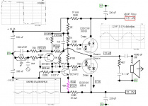
I took the liberty of committing nigel's circuit from post#5060 to LTspice. I modified his circuit to retro mode.
Please help me to simulate this circuit. THD, Sq, and Stability. One separate LTspice diagram for each parameter. This is for educational purposes only.
Also please an explanation of the resistor R3 and how its value is arrived at.
--gannaji.
I must say I didn't look too hard at that. With a class A amp I take 10kHz 10 watts as where I stop asking questions. My little class A using Exicon 10N/P 16 amp did 60 kHz full power with no real distortion. It didn't start like that.
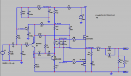
I had a better set of measurements from later ( lost ). Note the very local feedback loop to the VAS. It works. The amp is stupidly complex . Sorry so many graphs. Were so as not to forget details. It's class A + AB. The purple resistor became 16R. When 0R ( purple ) it's higher distortion. Self says otherwise. Too much loop gain isn't always ideal. It can mean more VAS capacitance to regain stability.
Note the 2u2 bootstrap capacitor. That was the point at which loop gain is not enough and distortion becomes greater ( 1 uF ). Self makes the same point except he can not accept extra low frequency distortion. When it's very good I might prefer the better quality capacitor. 10 uF polyester 100V type ideal. It is debatable if phase shift is more important and use something much larger. Listening test ( empirical ) required.
The 4000uF non polar output cap ( 4 x 1000 ) was for initial safety. Note very low offset. Zobel and output choke not really required. Choke was 16 turns 1 mm copper on 8 mm drill, 10 mm OD.
Attachments
That's great to see it as either good or bad it has a rightness about the idea. I was able to get more from my use of it. Also the output stage has a bit more current to waste than a VAS splitter. Both my amp and JLH are simple enough to make it not greatly different to the more conventional compensation. I doubt output triples would like it.
I agree that the response (shape) is critical for natural reproduction and that a specific rolloff within the audible band is a problem to that end. Not that a MW/AM broadcast can't be completely satisfying. A small error in the top end can mean the difference between feeling a presence and hearing a reproduction. It can also be affected by a speaker and by a room, sometimes to the point where it cannot be resolved.....music .... appreciates not having the corner removed.
The last time I bought a phono cartridge I supplemented its top end response by under-damping a resonance (something that the cable capacitance is connected with). If I remember correctly it was acceptable as it met a response need. However I don't know, the above quote seems oddly specific, for a blanket statement..Some say mildly unstable amps sound better, maybe?
- Home
- Amplifiers
- Solid State
- JLH 10 Watt class A amplifier