One week ago i was finished my new JLH monoblocks.
They based on JLH-2005 circuit with +-24v supply and 2.7A bias. I'm using two isolated capacitance multipiers per rail (with individual transformers too).
Amp was built on double sided PCB with ground poligon on top.
Transistors used :
2sa970BL->BD137(Philips)->MJL21194
More pics :
They based on JLH-2005 circuit with +-24v supply and 2.7A bias. I'm using two isolated capacitance multipiers per rail (with individual transformers too).
An externally hosted image should be here but it was not working when we last tested it.
Amp was built on double sided PCB with ground poligon on top.
An externally hosted image should be here but it was not working when we last tested it.
Transistors used :
2sa970BL->BD137(Philips)->MJL21194
More pics :
An externally hosted image should be here but it was not working when we last tested it.
An externally hosted image should be here but it was not working when we last tested it.
An externally hosted image should be here but it was not working when we last tested it.
just take a T-AMP, or 41Hz amp and tune it - its at least as good as a JLH, but you need speakers with sufficient sensitivy...
Ralf,
I agree up to a point. In a direct comparison the T-amp sounds clearly more accurate and less coloured, however my preference remains for the JLH due to its more relaxed and forgiving sound. Prolonged listening to the JLH is a pleasure and in my opinion it's sound is nicer, despite the T-amp's remarkable neutrality.
Tim.
PLEASE HEEEEEELP, why is my right channel repeatedly dying on me
I've build a JLH1969 with dual supply rails as in the jhlnotes article on Geoff's website.
Supply rails are +/- 23V. Iq is 1.0 A.
Heat sinks are massive (15 kg fanned aluminium per channel). Power supply is by capacitance multiplier.
The amp plays really nice, and even without the feedback capacitor the DC-offset is nice and stable as is the quiescent current which I've kept conservatively at 1.0 A.
BUT ... the right channel dies repeatedly (left never). Sometimes it plays for weeks, sometimes it plays for a few minutes or a few hours, but in the end I end up with two broken 2n3055 output transistors.
I've not a clue what's going on. Does anyone have any suggestions on how to debug because I'm getting desperate. It's sounds so nice ...
The following crossed my mind:
-input transistor: Earlier I had problems with 2n3906 which gave me blown output transistors. I've changed to BC560C, but could there be something slightly wrong. If so, how van I check?
-oscillation: Could it be that the amp sometimes starts oscillating. If so, how can I find out (I don't have a scope) or remedy in the first plave (preferably without adverse effects sound wise).
-the output transistors get hot after all without me noticing. I plan to put temperature sensors on the transistors to find that out.
PLEASE HELP

Thank you, MArco
I've build a JLH1969 with dual supply rails as in the jhlnotes article on Geoff's website.
Supply rails are +/- 23V. Iq is 1.0 A.
Heat sinks are massive (15 kg fanned aluminium per channel). Power supply is by capacitance multiplier.
The amp plays really nice, and even without the feedback capacitor the DC-offset is nice and stable as is the quiescent current which I've kept conservatively at 1.0 A.
BUT ... the right channel dies repeatedly (left never). Sometimes it plays for weeks, sometimes it plays for a few minutes or a few hours, but in the end I end up with two broken 2n3055 output transistors.
I've not a clue what's going on. Does anyone have any suggestions on how to debug because I'm getting desperate. It's sounds so nice ...
The following crossed my mind:
-input transistor: Earlier I had problems with 2n3906 which gave me blown output transistors. I've changed to BC560C, but could there be something slightly wrong. If so, how van I check?
-oscillation: Could it be that the amp sometimes starts oscillating. If so, how can I find out (I don't have a scope) or remedy in the first plave (preferably without adverse effects sound wise).
-the output transistors get hot after all without me noticing. I plan to put temperature sensors on the transistors to find that out.
PLEASE HELP
Thank you, MArco
Hallo
I also use a JLH69.
Volumecontrol is passive (20Klin.)
In comparising with a active pre. ,i can tell that de passive is the
better one.
The speakers are heresy,s (klipsch 96db)
In my opinion there is no need for using a active preamp when you are usingl speakers with a good output +92db
I also use a JLH69.
Volumecontrol is passive (20Klin.)
In comparising with a active pre. ,i can tell that de passive is the
better one.
The speakers are heresy,s (klipsch 96db)
In my opinion there is no need for using a active preamp when you are usingl speakers with a good output +92db
Re: PLEASE HEEEEEELP, why is my right channel repeatedly dying on me
Hello I have JLH 2004 version and it works without a problem (+-17V ->1.8A and capacitance multiplier). If you do not have a scope it is hard to check if you have an oscillation or not. But if your PCB is equal on both channels it is hardly unlikely that one oscillates and other not. Did you check that the DC voltages are the same on both channels, especially on the driver transistors? Maybe you have a bad solder and when the amp gets hot after some time you get the too much current at the output? Also, let the amp for a while running then quickly turn off and feel if the temperature on the output transistors is the same. Turn off since you have the potential on the TO3 transistors while it is on. They should be more or less the same. Maybe your thermal isolation on one of those is not good, do you use mica or just the paste? It is very important your thermal contact is good if not one of the channels (the left one in your case) maybe goes into the thermal runaway. Check first after 15min and then check after 1h and so on. Just to be sure. In the same time before that check the quality of solder joints. I would permanently monitor the current for a prolonged period of time to look for the thermal runaway effect (current will start to increase more and more faster and faster...)
If that does not help find somebody with the scope (it should be 100MHz to be sure) and then quickly check.
Regards,
Pred
deduikertjes said:BUT ... the right channel dies repeatedly (left never). Sometimes it plays for weeks, sometimes it plays for a few minutes or a few hours, but in the end I end up with two broken 2n3055 output transistors.
I've not a clue what's going on. Does anyone have any suggestions on how to debug because I'm getting desperate. It's sounds so nice ...
The following crossed my mind:
-input transistor: Earlier I had problems with 2n3906 which gave me blown output transistors. I've changed to BC560C, but could there be something slightly wrong. If so, how van I check?
-oscillation: Could it be that the amp sometimes starts oscillating. If so, how can I find out (I don't have a scope) or remedy in the first pl [/B]
Hello I have JLH 2004 version and it works without a problem (+-17V ->1.8A and capacitance multiplier). If you do not have a scope it is hard to check if you have an oscillation or not. But if your PCB is equal on both channels it is hardly unlikely that one oscillates and other not. Did you check that the DC voltages are the same on both channels, especially on the driver transistors? Maybe you have a bad solder and when the amp gets hot after some time you get the too much current at the output? Also, let the amp for a while running then quickly turn off and feel if the temperature on the output transistors is the same. Turn off since you have the potential on the TO3 transistors while it is on. They should be more or less the same. Maybe your thermal isolation on one of those is not good, do you use mica or just the paste? It is very important your thermal contact is good if not one of the channels (the left one in your case) maybe goes into the thermal runaway. Check first after 15min and then check after 1h and so on. Just to be sure. In the same time before that check the quality of solder joints. I would permanently monitor the current for a prolonged period of time to look for the thermal runaway effect (current will start to increase more and more faster and faster...)
If that does not help find somebody with the scope (it should be 100MHz to be sure) and then quickly check.
Regards,
Pred
Re: PLEASE HEEEEEELP, why is my right channel repeatedly dying on me
Something is different with the 2 channels. Take some voltage measurements to see if you can find any differences. Are some of the transistors getting hotter than others?
Something is different with the 2 channels. Take some voltage measurements to see if you can find any differences. Are some of the transistors getting hotter than others?
troubleshooting isn't easy ...
I did a major overhaull on my amp. The driver transistor in the right channel appeared to be bad. Replaced that one, and the output transistors of course.
It appeared that the left channel also had died. Replaced the output transistors and repaired a cold joint.
I've been measuring a lot with 0,3A Iq. The following happens:
right channel: stable as a rock 0,3 A.
Left channel: varying Iq, sometimes larger sometimes smaller while DC offset stays ok. Not a clue where that comes from. The DC measurements around the transistors all seem ok.
I've found a difference in left and right channel: the positive rail voltage on the left channel is almost 2 Volts lower than on the right channel and the negative rails. Would that be enough to explain the badly behaved right channel?
Apparently my capacitance multiplier is not fully correct. The adjustment trimmers only give me a variation of 0.1 Volts. I guess I have to dig into that one as well as It might be benificial to lower the rail voltages to about 20 volts.
Unfortunately I cannot check the temp of the transistors by feeling their cases (i have to take the amp apart for that). I can feel the alu where they are mounted on (with sil-pads). That never feels very hot (remember 15 kg of fanned aluminium on 2 output transisitors). Maybe I'll have to glue temp sensors on them, so I can watch them permanently.
Marco
Hi Marco
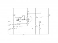
One design problem in the JLH which I have a concern with is that if the output were to clip, or even if the input signal were to be so fast that the driver could turn on quickly, the upper output transistor might be driven backwards.
In this case, the upper 2N3055 could be killed, due to excessive Vbe(reverse), and then the driver might be killed too.
Here's a pic where the circle illustrates the problem zone.
A solution might be to add a current limit in the driver and add a fast medium current diode in series with the base of the upper 2N3055.
If you have oscillation a small cap may help to suppress this. I've posted a circuit before with MJL3281's in the output (1592)
THe only other problem could be thermal runaway but with tons of heatsink I'd be surprised if this were the case...
cheers
John
Attachments
One design problem in the JLH which I have a concern with is that if the output were to clip, or even if the input signal were to be so fast that the driver could turn on quickly, the upper output transistor might be driven backwards.
Hmm, but I don't see many people complaining about killed transistors. But maybe mine is susceptible for this by having relatively high rail voltage with low Iq and driving speakers with don't have a very high impedance.
Can you please elaborate on that a bit. How to implement a current limit? Would that impair sound quality?A solution might be to add a current limit in the driver and add a fast medium current diode in series with the base of the upper 2N3055.
Would a series diode impair sound quality? Do you by any chance know of a suitable component number?
thanks very much, MArco
solved varying Iq
Solved this one:a faulty lead to my Volt-meter
MArco
Left channel: varying Iq, sometimes larger sometimes smaller while DC offset stays ok. Not a clue where that comes from. The DC measurements around the transistors all seem ok.
Solved this one:a faulty lead to my Volt-meter
MArco
Hi Marco
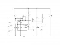
A couple of diodes for protecting the driver, and two possibilities for the upper 2N3055 diode.
Instead of connecting a diode in series, you could connect a diode in anti-parallel to shunt the reverse current in the base if it were to occur.
As long as the driver can take the power during short circuit/overload the upper 2N3055 should survive.
Diagram shows how.
You mentioned that you run your amp at high voltages. COuld you possibly be running your 2N3055's into their SOA limit?
Original RCA transistors did 1.9A @ 60V. Unless you use "H" versions you may not get this performance anymore. a few years ago, Motorola 2N3055's only did 2.9A @40V then downsized to 0.2A @ 60V.
Latest version from ON semi does 2.9A @40V, then downsizes to about 1A @ 60V - better than older devices but still not as good as RCA's.
If this is a problem you may want to try using MJ15003's or MJ21194's.
cheers
John
Attachments
Instead of connecting a diode in series, you could connect a diode in anti-parallel to shunt the reverse current in the base if it were to occur.
this seems the best solution to me. I'll try.
by the way, in my amp both the 2n3055 in a channel fail at the same time. I suppose the second one fails as a result of the failure of the first one under reverse bias?
You mentioned that you run your amp at high voltages. COuld you possibly be running your 2N3055's into their SOA limit?
the rail voltage is + and - 24-26 Volts. I'm using Toshiba 2n3055. Unfortunately i couldn't find a datasheet for that one, but I thought these where supposed to be quiet good.
I was planning to upgrade to mj15003 but I'd like to have the problems in the amp solved as these are quiet a bit more expensive as the 2n3055. But when the 2n3055 themselves are the problem this is quit a different story.
thanx, Marco
FaTTy: Nice amp and PCB's. What are the sexy TO-247 Caddock resistors for, outputs? ...and no heat sinks on them? ...are they just as good as the Mk.132's?
In the process of rebuilding my JLH. It needs a proper PSU and some other little things here and there. Mine is a 1969 original with BC560 -> 2N3019 -> MJ15003 (sampled and payed about $6.00USD and ON pulled and drop shipped from Digikey. They are like 4 hours away so $6.00 and a day later they where at my door). I must say I love it, it really slaughters my Sony surround in channel mode for music and I love watching movies on it too instead of the Sony in 5.1. I am still an infant in this high end audio/DIY thing, and now I am addicted, I have to many projects to list. Summer is about here though (college student) so it is time to build and overhaul. I am wondering if anyone has used the Jensen 4-poles or anything else interesting in the output of the 1969, or has bypassed them with films. This seems to be one of the weak spots in the original JLH. Would it be better just to switch to the split rail version, or the update with CCS's. I actually have one channel with CCS's partway built but just stopped building for some reason. Maybe I should finish that project. I am interested though how it will do against the Williamson style 807 amp and the Aleph 3 / J I am planning for summer, time and money permitting.
I am curious what line stage to mate with the JLH too. Right now I am using a ESP Project 88 that has LM4562's coming to it in about a day, UPS is slow. I hear the 4562's sound amazing, but I have never been all that sold on opamps. I have a pair of LM3875 amps (gainclones if you will) that I am constantly tweaking in hope that they will one day impress me. They are not bad for what you pay to buy the chips and build the amps, but they have not blown me away yet. I am itching to build a SuSy BPA300 though, a pair of PA150's with a Pass front end for the bridge, maybe that will impress...meah. Anyways I have a JFET BoZ and a simple 12B4 laying around in parts, no time to build with school. Just interested in what others are using.
Sorry to interrupt and thanks for the help both now and in the past when I was building (not on this thread but in general). I would take some pictures but the JLH is a mess, I need to build a case for it bad. Maybe I will take some in the near future just for fun. Happy listening and happy building to all.
Cheers
James
BTW: John: Have you built with the MJL3281's and how does it sound compared to the MJ15003's? Personally the 15003's are night and day compared to my very old but good RCA 3055's. I am curious how newer and faster transistors sound when the oscillation problem is fixed. I am thinking too about Sanken's and Toshiba's.
HI Marco
I don't know about the Toshiba 2N3055's. I suspect that they would be something like the early epi types with a relatively low Ic(max) at 60V. If you are running your JLH at +/-25V it MIGHT be that your 3055's are near the limit.
Toshiba devices appear to be quite widely "cloned", unfortunately. I may be wrong, but I think Toshiba gave up making 3055's some time ago as they have concentrated on the new fast high power devices like 2SA1302 (MJL1302 from ON semi etc).
James- yes, I've a MJL3281 version of the JLH. It's stable with a 47 pF capacitor across the feedback resistor and a 47 pF capacitor on the input base to ground. I think your line up is fine (BC560 2N3019). Many people overlook the importance of the input capacitor. It keeps the frequency response of the input stage high even if there is a load in series (external due to preamp output impedance etc).
I haven't had time to listen to it, yet! But the main difference is that on the bench, positive slew is tremendously fast compared with RCA 3055's. Those oldies could not drive even at 20 kHz (in simulation). Perhaps this is why some people can hear differences. The old RCA transistor had an fhfe of 10 kHz (min.) I typically measured 15 kHz. THe JLH amp original circuit did not have enough spare drive current to compensate for this for higher powers, but to be fair to JLH, he specified MJ481's I think, which are 4 MHz devices.
SO I have every expectation that the MJL3281 version will sound superb. When I get to listen!
Marco - I think that you may be near the limit of SOA for ordinary 2N3055's. You may like to try ON Semi 2N3055's in case their improved SOA helps. I suspect your amp may be oscillating too - this could reverse bias the base junction without you noticing (without a scope). You could try a 47 pF capacitor across the feedback resistor too even for "slow" 3055's. If the DC level changes it might indicate that that was a problem. Sometimes poor wiring can lead to oscillation (stray inductances, etc).
The simulated distortion for the protected JLH was the same as the unprotected one.
cheers
John
Morning John, look I just want to ask a simple question seeing as you raised the term in your last post. "stray inductance" (and for that matter "stray capacitance"). In some DIY circuits and designs without PCBs the instructions will casually say "be sure to minimise stray inductance/capacitance". Please can you briefly explain what that intails in practical terms? Thanks, Jonathan
Hi JamesFaTTy: Nice amp and PCB's. What are the sexy TO-247 Caddock resistors for, outputs? ...and no heat sinks on them? ...are they just as good as the Mk.132's?
Yes, i'm using this caddocks for outputs (they are in TO220-like, not 247). I think they don't need heatsinks beacuse of low power dissipation (approx 0.25W per each). Thay can handle up to 2W without heatsinks. Sorry, but i don't know what is "Mk.132" 🙂
I used old 2N3055s initially for my JLH amp, but was unable to set the bias properly (can't remember the exact details). Replacing them with the MJ15003 solved this.
I have also built an ESP P3A, and initially used 2N3055/MJ2955. When I replaced them with MJ15003 and its complement, the sound improved considerably. I would expect the same or even more difference with the JLH.
I have also built an ESP P3A, and initially used 2N3055/MJ2955. When I replaced them with MJ15003 and its complement, the sound improved considerably. I would expect the same or even more difference with the JLH.
FaTTy: IC, the Mk.132 is a 3/4watt precision resistor from Caddock that gets a lot of talk for it's audio qualities. I have yet to try them but they are said to sound better than the Vishay/Dale RN's and close to or better than tantalums(?). Very clean and lots of detail, but they cost anywhere from $3-$7 USD. Borbely Audio and Welborn Labs use them in some of their premium kits.
http://www.caddock.com/Online_catalog/power/Power.html
Bottom of the page on the left, the MK Series. I have always wanted to try Caddocks and was wondering if you have tried wire wounds or anything else and liked the sound of the Caddocks, or if it was just what was available. Either way, again a very nice looking build.
"I would expect the same or even more difference with the JLH" - Paulb
I saw...edit heard, a pretty large difference moving from the 3055's to the 15003's. Keep in mind though that my 3055's where RCA's, old transistors, older than I am, of course I am just a youngin'. I was kind of surprised though that I sampled them, got them, dropped them in, and it worked just fine! I switched back and forth once, and then kept 3055's in one channel and 15003's in the other to compare them. The 3055's seemed almost to mask some of the sound, it sounded almost muffled and just as not quite right. The sound was still better than my Sony, but it was still kind of flat and muffled. The top end wasn't bad but the low end wasn't quite as tight and focused. When I went to the 15003's, honestly, this all went away. The sound was open and natural, yet clean, focused and a lot tighter, especially in the low end. The sound stage was much more 3D, the curtain was lifted, literally it sounded like something was draped in front of the speakers before with the RCA's. I noticed it a lot more too when I watch movies on the amplifier. Everything was tight and controlled, it seemed like I could connect more with the actors. The movie was also more "around me" without having more than two speakers. Just the other day I watched Smokin' Aces and was impressed, even during the chaotic gunfight scenes where there was lots and lots of sound nothing was muffled or left out, it was all there. I like it when an amp I built almost two years ago that needs lots of improvements can still impress me.
I would say if you are thinking about the 15003's, just do it and don't look back. They are a bit on the pricey side...unless you sample them for $6 per 4, $1.50USD apiece isn't to bad when Mouser has them for $3.29 each plus shipping 🙂 . I would just do it, pop them in, listen to the new wonderful sound, and not look back. Though now I have an itch to try John's version with high speed trannies, MJL3281's sounds good but maybe some 3SC5200's or some 2SC3264's with some fast and quiet Toshiba front end transistors , the JLH from hell.
Cheers
James
BTW: Paulb - You can use transistors like the MJL4281 in the ESP P3A without any problem. They are super fast, linear, and according to Mr. Elliott the P3A sounds it's best with these kinds of transistors. You could also try the well regarded 2SC5200 (watch out for fakes) or the super fast (faster then the MJL4281) 2SC3264, it's in a funny package though, Sanken MT-200 package instead of TO-247 / TO-264. You would have to use the compliments in the P3A of course as well.
http://www.caddock.com/Online_catalog/power/Power.html
Bottom of the page on the left, the MK Series. I have always wanted to try Caddocks and was wondering if you have tried wire wounds or anything else and liked the sound of the Caddocks, or if it was just what was available. Either way, again a very nice looking build.
"I would expect the same or even more difference with the JLH" - Paulb
I saw...edit heard, a pretty large difference moving from the 3055's to the 15003's. Keep in mind though that my 3055's where RCA's, old transistors, older than I am, of course I am just a youngin'. I was kind of surprised though that I sampled them, got them, dropped them in, and it worked just fine! I switched back and forth once, and then kept 3055's in one channel and 15003's in the other to compare them. The 3055's seemed almost to mask some of the sound, it sounded almost muffled and just as not quite right. The sound was still better than my Sony, but it was still kind of flat and muffled. The top end wasn't bad but the low end wasn't quite as tight and focused. When I went to the 15003's, honestly, this all went away. The sound was open and natural, yet clean, focused and a lot tighter, especially in the low end. The sound stage was much more 3D, the curtain was lifted, literally it sounded like something was draped in front of the speakers before with the RCA's. I noticed it a lot more too when I watch movies on the amplifier. Everything was tight and controlled, it seemed like I could connect more with the actors. The movie was also more "around me" without having more than two speakers. Just the other day I watched Smokin' Aces and was impressed, even during the chaotic gunfight scenes where there was lots and lots of sound nothing was muffled or left out, it was all there. I like it when an amp I built almost two years ago that needs lots of improvements can still impress me.
I would say if you are thinking about the 15003's, just do it and don't look back. They are a bit on the pricey side...unless you sample them for $6 per 4, $1.50USD apiece isn't to bad when Mouser has them for $3.29 each plus shipping 🙂 . I would just do it, pop them in, listen to the new wonderful sound, and not look back. Though now I have an itch to try John's version with high speed trannies, MJL3281's sounds good but maybe some 3SC5200's or some 2SC3264's with some fast and quiet Toshiba front end transistors
, the JLH from hell.Cheers
James
BTW: Paulb - You can use transistors like the MJL4281 in the ESP P3A without any problem. They are super fast, linear, and according to Mr. Elliott the P3A sounds it's best with these kinds of transistors. You could also try the well regarded 2SC5200 (watch out for fakes) or the super fast (faster then the MJL4281) 2SC3264, it's in a funny package though, Sanken MT-200 package instead of TO-247 / TO-264. You would have to use the compliments in the P3A of course as well.
Hi Jonathan
Every wire has built-in inductance and capacitance! Inductance effects can be magnified if the wires carrying a current enclose a large area. To minimise the effects, the area enclosed by a signal wire and its return lead should be as small as possible. Usually this means using twisted pairs - for example, loudspeaker output and its ground return inside the amp - and in the case of power supply leads (three- positive, negative and ground) these can be twisted, or, my preference, is to plat (plait) them as this holds them together better. Also it looks like a three-phase signal diagram! Although this minimises inductance effects, it increases capacitance between the wires. This usually isn't important because large capacitors tend to be wired across power leads in any case to smooth the signals.
But stray capacitance between the output and a sensitive signal lead can sometimes cause oscillation. I have found that transistor circuits tend not to suffer from this too much but valve amplifiers which responded more by electrostatics than current devices tended to be very sensitive to stray capacitance effects.
cheers
John
JPeitzman
I do not have extensive experience of application of various high-quality resistors in audio devices. But I have constructed some variants of this amplifier with use of various parts. With caddocks my amplifier sounds very purely and openly. As a matter of fact these resistors the best that I could get for that moment so i used them and not be dissapointed all the ways 🙂
I do not have extensive experience of application of various high-quality resistors in audio devices. But I have constructed some variants of this amplifier with use of various parts. With caddocks my amplifier sounds very purely and openly. As a matter of fact these resistors the best that I could get for that moment so i used them and not be dissapointed all the ways 🙂
- Home
- Amplifiers
- Solid State
- JLH 10 Watt class A amplifier