Hi again Nigel,
you mentioned your Garrard 401 - I also have one of these beasties coupled with a SME 9 inch arm and a Ortofon Black cartridge
However, the rumble has become apparent after lack of use for a year or so. I have 'anointed' the motor and idler bearings with the appropriate oil (fine sowing machine oil from my wife's collection, as specified in the manual) and cleaned the inside rim of the platter. Have you had cause to do more than this?
Kind regards
Mike
The best rumble we got from a 401 was about -57dB weighed. The 501 I helped design -78 dB. To be honest I am happy with the 401. The 501 is mostly the same design. Like this amplifier small details can eventually pay off. Early 501 was -69 dB which is about 3dB worse than a LP12. Many cutting lathes about like a 401.
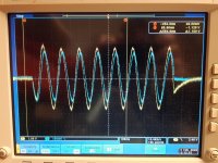
Since I saw the strange transient behavior in simulation, I did a measurement with a 10Hz sine burst, and could see the same thing.
Blue is input, yellow is output on the scope.
I attached a scope picture and a simple schematic of it after some mods (had TIP41C in the kit).
Blue is input, yellow is output on the scope.
I attached a scope picture and a simple schematic of it after some mods (had TIP41C in the kit).
Attachments
Maybe parallel 1000 uF on the lower feedback arm. It should be close to DC then. If it works tune it. 10 minute mod. Doubtless ears and oscilloscope can choose an ideal value. Try a smaller bootstrap capacitor. Larger also. At low frequencies the bootstrap works in a slightly mysterious ways.
I tried a 4700uF parallel with the feedback cap, and saw no change, then moved it and paralleled it with the bootstrap, and no change..
EDIT: Output cap has some influence, the 'offset' at the end of the burst is 0,4V before the output cap, and 1V after. This is with 4700uF in parallel with feedback and bootstrap caps.
EDIT: Output cap has some influence, the 'offset' at the end of the burst is 0,4V before the output cap, and 1V after. This is with 4700uF in parallel with feedback and bootstrap caps.
Last edited:
Ok, soldered a 200uF over the input cap too, and now I have a good looking signal before the output cap (no offset), and the 'offset' at the end of the burst is abt 0,5V after the output cap now.
To 'recap': the input cap is 202uF, feedback cap 5,1mF, bootstrap 5,7mF, output cap 10mF, load resistor 7Ohm.
To 'recap': the input cap is 202uF, feedback cap 5,1mF, bootstrap 5,7mF, output cap 10mF, load resistor 7Ohm.
That rules out the easy things. Good thing really. It's not PSU related as the simulation does it also. It isn't the PSU filter capacitor if added to the switch mode power supply. I imagine ( RC time constant ) That wouldn't be in the SIM I guess?
Actually, I do have a linear PSU in the simulation I played around with. Not very accurate for sure, but it has a rectifier and smoothing caps, and some R & L in series with the AC sources.
However, these real world tests have been done with a stabilized bench supply. Only drawback of that is a max current of 1A on the supply, so I'm not able to 'crank it up'. However, supply voltage is pretty stable.
I think the over-sized feedback and bootstrap caps did not do much, I think I should try to go back to the previous values on those. Seems like it was more the input and output caps causing it.
Last edited:
What you are seeing is simply the effects of low frequency time constants. As you have found there are three main ones (1) the inputl (2) the feedback and (3) the output.
These will always have 2 zero crossings after a transient (zero crossings= n-1). As you have also found it is a matter of making them compatible and low enough not to matter.
I have not found 10mF on the output adequate for good LF response. It probably needs to be around 22mF. Try square wave testing to check where the LF time constants are.
Hi John. My brother did a lot of repairs. Experience led him to think time constants were a secret quality of good sound. He thought amplifiers that had nothing in common as far as topology was concerned might sound similar. He believed it wasn't the absolute time constants but being careful to listen to them. I recently reduced the PSU capacitors in my NAD 3020. This was initially because I only had a certain cap. I then bought a high grade of a similar value. The effect was to reduce boominess. The speakers no doubt being the cause. I only mention this as it is counterintuitive.
Member
Joined 2009
Paid Member
What you are seeing is simply the effects of low frequency time constants. As you have found there are three main ones (1) the inputl (2) the feedback and (3) the output.
These will always have 2 zero crossings after a transient (zero crossings= n-1). As you have also found it is a matter of making them compatible and low enough not to matter.
I have not found 10mF on the output adequate for good LF response. It probably needs to be around 22mF. Try square wave testing to check where the LF time constants are.
Excellent post, I get distracted by the active devices but this amplifier is way more than that.
Nigel, I think in the early days of tranny amps, it seems that 2mF was always the "standard" output cap. Many designs however varied. Some had feedback from the speaker, including the cap in the loop. Those, I think, were dreadful. While they may have extended the LF response at low volume, they were unable to maintain full power at the extended low frequencies, so would have clipped even worse had they not included the cap in the loop.
And, coupled with speaker variants, some might have used the roll off to mask poor distortion etc. So I'd agree that the cap value would have been used with varying effects. Back then, but not now, I would suggest.
And, coupled with speaker variants, some might have used the roll off to mask poor distortion etc. So I'd agree that the cap value would have been used with varying effects. Back then, but not now, I would suggest.
Hi folks,
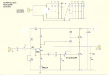
Staying inside and away from Storm Ciara,( or Dennis/whatever the latest one is named) I decided to have a play with using Sziklai pairs as the output devices on a JLH amp in LTSpice. Here are the results so you can play with the simulations yourselves. The sim files and all the transistor models are in the attached zip file alond with some alternative devices such as the MJE2955 and 2N2955.
The basic amp is the Geoff Moss version of the JLH that uses symmetrical power supplies and 2, CCS to adjust the output offset and quiescent current. In the simulation files I have used fixed resistors and simply adjusted their values by hand. If there are any glaring mistakes, please post them here so we can all learn.
The usual caveats apply: this is a simulation, it assumes perfect and matched devices etc. I have no idea about how it will sound – that’s a summer project. 😊
The output pairs consist of BD139C coupled with a MJ15004 to do the heavy lifting and a 2SC3421 as the driver/phase splitter. I tried a BD139 in this position but it became unstable at low currents and low outputs. The slug 100pF cap is still in the circuit but not connected.
The circuit has 4 sets of output pairs so one can adjust the number to suit your own needs – just delete the appropriate pairs and associated decoupling caps. As you will see, I am a fan of using multiple output pairs as it spreads the load and heat dissipation across the output devices and keeps them on the fairly linear/optimum portion of the hfe vs collector graph. The loudspeakers I use are B&W 801 series 3 monitors which can dip below 6 ohms impedance so require quite a bit of current to drive them.
In the circuit diagram, R1 is the adjustment of the quiescent current and R13 for the output DC offset. Interestingly, I found that there is less interaction between them when using S-pair output stages. I also tried adjusting the 8k2 collector load of the input device, in my case a 2SA970. Taking it down to 6K8 made quite a lot of difference.
The table of results is a bit of a swine to tabulate so I have included a spreadsheet in the attached zip file.
The table shows how the experimenting went: the main adjustment was to vary the Iq so as to achieve the minimum THD figure at low power. This was done at an output power of 1 Watt into 6 ohms. You can see the effect of altering the Collector load (R7) from 8K2 to 6K8.
That adjusts the bottom end of the Iq but then we need to find a compromise in increasing Iq so as to get maximum output and this appears to be adjusting for about 2 Amps per device. Too less a Iq leads to a ‘dog leg’ in the bottom peak of the sinusoidal output.
I was also pleasantly surprised how much (simulated) power the amp can deliver. My current amp uses standard emitter followers (4 off) and achieves about 75 to 80 watts output into 8ohms whereas this version appears to get up to 90 watts or so.
Regards, Mike
Attachments
Thank you John. I'm aware of the RC constants from school sometime long ago, but not really keen on calculating stuff ") A bit complex co calculate how it all adds up at the output of the amp too I would think.
A bit complex co calculate how it all adds up at the output of the amp too I would think.
I'd rather change the values in the sim (now that I have finally been able to get a sim running), or just solder on/off some caps and try.
I did solder off some of the extra caps and try again, and the bootstrap cap is fine at 1000uF (could be ok with smaller too), but the feedback cap is too small at 470u. I guess the 1000u I simulated before could be a reasonable value.
Input cap I don't know yet, only that 2,2u is too small. Maybe 10u or more would be good.
As you say, output cap still seems to small at 10mF, I once listened to one with a 4,7mF output cap and thought it sounded pretty good in the bass, but that would have a lot to do with the combination together with the speakers impedance and LF response too.
I find it a bit strange that such low cap values were selected by JLH from the start?
A bit complex co calculate how it all adds up at the output of the amp too I would think. I'd rather change the values in the sim (now that I have finally been able to get a sim running), or just solder on/off some caps and try.
I did solder off some of the extra caps and try again, and the bootstrap cap is fine at 1000uF (could be ok with smaller too), but the feedback cap is too small at 470u. I guess the 1000u I simulated before could be a reasonable value.
Input cap I don't know yet, only that 2,2u is too small. Maybe 10u or more would be good.
As you say, output cap still seems to small at 10mF, I once listened to one with a 4,7mF output cap and thought it sounded pretty good in the bass, but that would have a lot to do with the combination together with the speakers impedance and LF response too.
I find it a bit strange that such low cap values were selected by JLH from the start?
Interesting stuff Mike! I will download and see if I can get your sim running later.
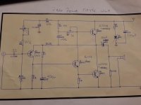
As for now, I just wanted to post a schematic of what I have done with the Zero Zone PNP JLH.
The changes in the schematic are from memory, so there might be some errors and mistakes, but if I wait longer, there will surely be things forgotten, so I decided to make it now.
This is my everyday amp at the moment, and I love the sound it makes, and it also measures better (at 8 ohm load) than any other JLH I have.
Attachments
Hi folks,
Staying inside and away from Storm Ciara,( or Dennis/whatever the latest one is named) I decided to have a play with using Sziklai pairs as the output devices on a JLH amp in LTSpice. Here are the results so you can play with the simulations yourselves. The sim files and all the transistor models are in the attached zip file alond with some alternative devices such as the MJE2955 and 2N2955.
The basic amp is the Geoff Moss version of the JLH that uses symmetrical power supplies and 2, CCS to adjust the output offset and quiescent current. In the simulation files I have used fixed resistors and simply adjusted their values by hand. If there are any glaring mistakes, please post them here so we can all learn.
The usual caveats apply: this is a simulation, it assumes perfect and matched devices etc. I have no idea about how it will sound – that’s a summer project. 😊
The output pairs consist of BD139C coupled with a MJ15004 to do the heavy lifting and a 2SC3421 as the driver/phase splitter. I tried a BD139 in this position but it became unstable at low currents and low outputs. The slug 100pF cap is still in the circuit but not connected.
The circuit has 4 sets of output pairs so one can adjust the number to suit your own needs – just delete the appropriate pairs and associated decoupling caps. As you will see, I am a fan of using multiple output pairs as it spreads the load and heat dissipation across the output devices and keeps them on the fairly linear/optimum portion of the hfe vs collector graph. The loudspeakers I use are B&W 801 series 3 monitors which can dip below 6 ohms impedance so require quite a bit of current to drive them.
In the circuit diagram, R1 is the adjustment of the quiescent current and R13 for the output DC offset. Interestingly, I found that there is less interaction between them when using S-pair output stages. I also tried adjusting the 8k2 collector load of the input device, in my case a 2SA970. Taking it down to 6K8 made quite a lot of difference.
The table of results is a bit of a swine to tabulate so I have included a spreadsheet in the attached zip file.
The table shows how the experimenting went: the main adjustment was to vary the Iq so as to achieve the minimum THD figure at low power. This was done at an output power of 1 Watt into 6 ohms. You can see the effect of altering the Collector load (R7) from 8K2 to 6K8.
That adjusts the bottom end of the Iq but then we need to find a compromise in increasing Iq so as to get maximum output and this appears to be adjusting for about 2 Amps per device. Too less a Iq leads to a ‘dog leg’ in the bottom peak of the sinusoidal output.
I was also pleasantly surprised how much (simulated) power the amp can deliver. My current amp uses standard emitter followers (4 off) and achieves about 75 to 80 watts output into 8ohms whereas this version appears to get up to 90 watts or so.
Regards, Mike
I got your sim running on first try, quite a 'beast' you have there!
To continue my 'investigation' on cap values, I tried some values for C2(input) and C3(feedback) in your sim using 3 periods of 20Hz as input. Using C2 10u and C3 1000u improved the offsets in the beginning and at the end of the burst significantly. Going to 47u and 4700u makes it close to perfect. Just a matter of what space is on the board I guess. For my amps I have ordered some 1000u bipolars from Digikey for feedback caps, and waiting delivery.
I have one of the Chinese ones on loan at the moment.What a frustrating amp!It nearly sounds really good but is let down by a very 2D soundstage and a slight dryneess to the midrange. Too much negative feedback?The treble is beautiful and pure and it is even quite musically engaging but I can"t stand listening for too long because of the flatness.
Like this one-or the same chasis anyway.
https://ae01.alicdn.com/kf/HTB1zwQZHpXXXXXCapXXq6xXFXXXC/200624125/HTB1zwQZHpXXXXXCapXXq6xXFXXXC.jpg
Like this one-or the same chasis anyway.
https://ae01.alicdn.com/kf/HTB1zwQZHpXXXXXCapXXq6xXFXXXC/200624125/HTB1zwQZHpXXXXXCapXXq6xXFXXXC.jpg
I have one of the Chinese ones on loan at the moment.What a frustrating amp!It nearly sounds really good but is let down by a very 2D soundstage and a slight dryneess to the midrange. Too much negative feedback?The treble is beautiful and pure and it is even quite musically engaging but I can"t stand listening for too long because of the flatness.
Like this one-or the same chasis anyway.
https://ae01.alicdn.com/kf/HTB1zwQZHpXXXXXCapXXq6xXFXXXC/200624125/HTB1zwQZHpXXXXXCapXXq6xXFXXXC.jpg
Read the thread and start tweaking
First thing you can do is tune the Iq (standing current), I guess there should be trimmers for that? Power supply caps size looks a bit small? Other caps, other transistors etc..
You could reduce the negative feedback. The effect would be slightly more like the sound of a good tape recorder or valve amplifiers. The extra sensetivity could be useful. As it's class A higher order distortion should remain reasonable. Adjust the lower feedback resistor next to the capacitor. If you parallel a resistor of the same value that would be about where to start. That way no need to remove anything. If you change the upper feedback resistor the DC mid point moves. I believe all amplifiers have ideal gain that has to be found. My old Quad 33 303 has a spare input called Radio 2. If I an right it works with older valve equipment. Usually it sounds awful. One day I took pen and paper to build a bespoke phono stage around it. My hunch was an op amp could not only amplify, it could match the needs of impedance. I was astonished by how good it was. What seemed to be working was ideal gain and matching.every technical parameter. Like having exactly the right gear ratios for an engine. That was one thing the Quad had in it's favour was a higher sensitivity. This allowed me to just about get an op amp to do the full gain required. That could require a gain of 1000 at 20 Hz. Surprisingly that's not out of the question. I used about 60 at 1 kHz being circa 600 at 20 Hz.. Distortion circa 0.2% worst case.
Last edited:
- Home
- Amplifiers
- Solid State
- JLH 10 Watt class A amplifier