Would be possible to have the option of a complete kit ?
Very hard for me to source the parts , I believe many people would appreciate and probably more buyers
Hi, if the post is intended for me, sorry, I no longer have for sale, any PCB's (or components thereof).
Its for my own personal build.
If successful, I shall offer the spare PCBs to forum members at an appropriate price.
thanks and regards
Prasi
Hello Gabor,
any update on your build?
regards
Prasi
No I only finalized the PC board layout, I do not found clad board the size I need. 31*7.5Cm I found in US but with shipping it cost $22 US plus import duty. Too much! There is local store a bit far away from I live, I did called them (I called many other store), they have some type. I have to make that trip to visit that store. If the copper to thin is useless. I would like to get 2oz copper at least for Class A.
I will do these project!
Thanks for asking
")
Attachments
My lay out is much larger, so you can not just print it out for iron transfer.
Please you take it into the paint and print set up and print it out from there for the right size! That is how I draw my layouts, in these case Prasi's layout modified to 100% feet my heatsink. Thanks to Prasi
Working with paint (program) easier to work if the layout larger. Please do not forget there is a GB and if you need PC boards please participate to get high quality commercial grade boards for less $ than it will cost to me. I only chose these option because my heatsinks shape and size.
Hi Gabor, one suggestion, if I may make.
Since you are doing many layouts or modification work in paint, you could get sprint and it will be very easy.
Sprint is very intuitive and you would be able to make first design in hours.
I guess you are already aware of this , but wanted to suggest.
You could import any Gerber's in sprint.
There is very good tutorial by Juan Vargas on YouTube on sprint.
Even from jpeg layout picture , even a new person, could create a clone layout in 1-2 hours.
Regards
Prasi
Hi Gabor, one suggestion, if I may make.
Since you are doing many layouts or modification work in paint, you could get sprint and it will be very easy.
Sprint is very intuitive and you would be able to make first design in hours.
I guess you are already aware of this , but wanted to suggest.
You could import any Gerber's in sprint.
There is very good tutorial by Juan Vargas on YouTube on sprint.
Even from jpeg layout picture , even a new person, could create a clone layout in 1-2 hours.
Regards
Prasi
I have the Sprint! Just don't know how to use it. Also I got use to it to paint. More than 10 years experience. I tried Sprint and just confusion and confusion. To me waste of time.
I do not have time and patience to learn that to from the beginning.
Paint takes much more time (10x) and patient but I got the experience
Thanks for the advise
Greetings gabor
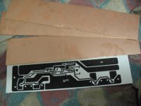
Today I got some clad board for these project.
A bit thick boards 2MM or 2.2mm and double sided. I only found these with thick 2 or 3 oz copper.
I will pull the copper of from one side, will take some effort and elbow grease
The store had one sided clad boards but a few mm shorter what I need and only with thin 1 oz copper.
Just need to find some 12.5" long photo paper to transfer the image. I may glue two paper together if Staples will not have.
Some small progress.
Attachments
Today I got some clad board for these project.
A bit thick boards 2MM or 2.2mm and double sided. I only found these with thick 2 or 3 oz copper.
I will pull the copper of from one side, will take some effort and elbow grease
The store had one sided clad boards but a few mm shorter what I need and only with thin 1 oz copper.
Just need to find some 12.5" long photo paper to transfer the image. I may glue two paper together if Staples will not have.
Some small progress.
Why don't you just reduce the board size to fit on one sheet? Much easier than what you otherwise plan to do.
Besides it looks like you can actually paint the board with something suitable , like nail polish ?, for the tracks. The layout is very simple and without any complications. Have you ever tried this ? I used to do that for years a long time ago. Put the design on the board , drill through all the holes and then paint on the tracks ! Etch it. The second side will get removed also . You will need nail polish, a thinner ( like amyl acetate or acetone ) a small container to thin the nail polish ( maybe NC paint used in cars is also OK ?) a thin paint brush and a thicker one for wide spaces. Amyl acetate dries slow enough to give you time to spread it around easily. NC paint ( with thinner) might dry more rapidly. But then you can scrape away excess very easily as the paint will crack away cleanly and not tear and come off in strands. Use a regular box cutter knife ( or just the blade !) to clear up excess paint or clean up edges.
Alternatively you can use masking tape to block out the parts to be etched away and spray the board with an aerosol can of paint. Remove the tape after it dries , paint on any small complex sections with a brush and etch it !
PS. I still use the nail polish method for very small simple boards as it's super fast. From drilling to ready board in under an hour ! You need to have a steady hand to make it look neat. But you can use guides like rulers etc. to get straight lines.
Last edited:
Greetings, allow me to ask some questions to help me build a JLH for the first time.
I bought this board on eBay:


There are two pairs of trimpot, one pair right behind input caps, and the other pair before the output. I don't have any schematic but probably you gentlemen knew this design inside and out and can tell me what they are doing and how to set them.
This is my first discrete amp build, and I have never tried to bias an amp.
The ad says 16VDC power supply. How much capacitance is needed for this amp? Thank you for your guidance.
Greetings, allow me to ask some questions to help me build a JLH for the first time.
I bought this board on eBay:
An externally hosted image should be here but it was not working when we last tested it.
An externally hosted image should be here but it was not working when we last tested it.
An externally hosted image should be here but it was not working when we last tested it.
There are two pairs of trimpot, one pair right behind input caps, and the other pair before the output. I don't have any schematic but probably you gentlemen knew this design inside and out and can tell me what they are doing and how to set them.
This is my first discrete amp build, and I have never tried to bias an amp.
The ad says 16VDC power supply. How much capacitance is needed for this amp? Thank you for your guidance.
this is where the chinese aliexpress's and alibaba's and chisene ebay's fail miserably. They dont provide proper documentation lest a schema atleast!.
horrible way to do business in international market.
sorry friend I cant (I am newbie) help and even expert designers may not be able to help you without a schema.
one can take a wild guess that one trimpot is for offset and other for bias, but its just that, a wild guess!.
ask for some customer support or contact someone who has already built this particular version.
its all i can say.
do i see mosfet o/p? irf's?
Greetings, allow me to ask some questions to help me build a JLH for the first time.
I bought this board on eBay:
There are two pairs of trimpot, one pair right behind input caps, and the other pair before the output. I don't have any schematic but probably you gentlemen knew this design inside and out and can tell me what they are doing and how to set them.
This is my first discrete amp build, and I have never tried to bias an amp.
The ad says 16VDC power supply. How much capacitance is needed for this amp? Thank you for your guidance.
Hi
It looks to me these is a Stereo PC board layout.
Hard to be sure because the picture is in a certain angle almost impossible to read the components.
Based on the size of the power devices very likely it is a JLH head phone amp. It can not be a full size power amp even if we talking about 8W or so.

Well known the JLH is a Class A amp.
Can you post other picture from the top so we can see and read the parts better.
Greetings
I made some search on the net, did not found one like yours only something similar.
Assembled TIP41C-JLH1969 single-ended class A Power amp board ( 2 CH) | eBay
I think your amp is like these only yours is a stereo version.
What I don't understand how they can claim is a 10W power @ 4R
Very likely it is a Class A/B amp low bias.
Assembled TIP41C-JLH1969 single-ended class A Power amp board ( 2 CH) | eBay
I think your amp is like these only yours is a stereo version.
What I don't understand how they can claim is a 10W power @ 4R
Very likely it is a Class A/B amp low bias.
Prasi, yes I know it is bad. I got if almost 7 months ago but hesitated to build it because it doesn't come with a schematic. Regarding output transistor, vipco is right.this is where the chinese aliexpress's and alibaba's and chisene ebay's fail miserably. They dont provide proper documentation lest a schema atleast!.
horrible way to do business in international market.
sorry friend I cant (I am newbie) help and even expert designers may not be able to help you without a schema.
one can take a wild guess that one trimpot is for offset and other for bias, but its just that, a wild guess!.
ask for some customer support or contact someone who has already built this particular version.
its all i can say.
do i see mosfet o/p? irf's?
This is why I turn to you guys, I hope somebody might have built it, or is familiar with the layout. I will take some pictures and hopefully show you better detail.
No, it's not for headphones. This is a low-power version. Output transistors TIP41C one pair per channel. There are two channels on this board. At a voltage of 16 volts, the power will be 3 watts at 8 ohms.
Thanks vipco, that is exactly what it says on the listing. Here it is:
New DC 12-33V Fever 1969 Small Class A Amplifier Board Module DIY Kits | eBay
....I bought this board on eBay:
I have to update a so called Photobucket account, which I don't have, nor want, to see the board. Why not simply attach it, so all can see?
I have to update a so called Photobucket account, which I don't have, nor want, to see the board. Why not simply attach it, so all can see?
Read this:
http://www.diyaudio.com/forums/foru...king-free-inline-img-hosting.html#post5121868
- Home
- Amplifiers
- Solid State
- JLH 10 Watt class A amplifier