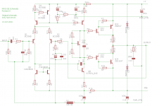
Here is the schematic for the MX50SE kit by LJM that can be had on Ebay for about $18 USD shipped. I have not really hammered on the board yet so I wont comment on performance but clearly for the cost it is a great deal. The circuit is also interesting looking. I believe it is a rip-off of the Musical Fidelity X-A50? I would be curious to know if it is a clone or of this LJM character contributed some intelligence to the circuit. Someone deserves some credit.

This simulates fine. Note that the schematic posted with the Ebay listings is totally bogus. And the transistor listed as "5551" is not a 2N5551. It has to be a transistor with pinout ECB. Then it makes sense and simulates well.
Anyway, hopefully no one gets bent for posting this. But I would say it only makes Musical Fidelity and / or LJM look good. So either buy some MF gear or make something with the super cheap boards and if someone knows who the real brains are behind the circuit please enlighten us.
Attachments
Last edited:

Looks like a fairly standard circuit with CFP output, save for one detail - a bootstrapped current source. I suppose one of R21/22 would have to be a pot?
Looks like a fairly standard circuit with CFP output, save for one detail - a bootstrapped current source. I suppose one of R21/22 would have to be a pot?
No, they're just 1k resistors. What would the pot do? I think the bias is probably fine. I don't want to post numbers because my test rig is not precise enough and I only tested with a 100 ohm load but distortion does not look like a problem. At least the SNR is about ~85dB and that is with 30dB of gain so that gives a SNR of 115dB? If yes, I would say distortion isn't an issue (although again, that was with a 100 ohm load because I was just sanity checking the circuit).
One interesting think about the two boards I built is that one has an offset of ~34mV and the other has an offset of 0mV. And I mean absolutely *zero*.
What would be the most likely cause of offset? The 10K resistors on inputs are closely matched. Should I try matching transistors?
Last edited:
Here is the schematic for the MX50SE kit by LJM that can be had on Ebay for about $18 USD shipped. I have not really hammered on the board yet so I wont comment on performance but clearly for the cost it is a great deal. The circuit is also interesting looking. I believe it is a rip-off of the Musical Fidelity X-A50? I would be curious to know if it is a clone or of this LJM character contributed some intelligence to the circuit. Someone deserves some credit.
This simulates fine. Note that the schematic posted with the Ebay listings is totally bogus. And the transistor listed as "5551" is not a 2N5551. It has to be a transistor with pinout ECB. Then it makes sense and simulates well.
Anyway, hopefully no one gets bent for posting this. But I would say it only makes Musical Fidelity and / or LJM look good. So either buy some MF gear or make something with the super cheap boards and if someone knows who the real brains are behind the circuit please enlighten us.
This amp is a clone of Douglas Self's "Blameless Amp", with CFP outputs (Self uses EF). The design is published in Self's many books and articles. The front end is an almost exact copy including passive component values. Compared to EF outputs, the CFP output stage is excellent because it gives lower distortion and lower bias current for cool running. So, overall this amp sounds good, is simple, cheap and tiny, and for price is hard to beat.
It has limits, imposed by its low cost. It is rated 50 Watts output at +-45VDC supply, which it delivers, but that's the max. These limits should not be exceeded for several reasons. First, the electrolytic capacitors are rated 50v, and they will eventually leak, bulge or explode if used at higher voltages. Second, the 1815 transistors are rated for 50v Vceo, and must be used below this rating or they may fail. Third, the output transistors are already outside their safe operating area and can fail if driven hard into low impedance or reactive loads. So the 45 volt supply limit is very real and should be followed. For 4 ohm loads, you must lower the power supply voltage or you will burn out the output transistors.
You can beef this up to get a little more power, but it's risky. You can replace the 50 volt capacitors with 63v, and change the 1815 transistors to higher voltage parts which will have different pinouts. But it's risky, because the output stage is already at risk for exceeding safe operating area and failing in second breakdown, especially with low impedance reactive loads like most real world speakers. Rather than tweaking this design, you can find better starting points for almost the same price.
This designer, LJM, has a family of good kit amp designs sold by many Chinese dealers on ebay and elsewhere. This model, the MX50 SE, is fine up to 50 watts. The next step, LJM's L12-2, is a better choice up to 100 watts. It has essentially the same front end but doubled output transistor pairs and uprated capacitors, so it's OK for higher power. For even more power, LJM's L20 SE gives 200 watts. The L20 SE has quadrupled output transistor pairs and MOSFET drivers, but the front end is essentially the same. LJM has other amps of different design (some digital, some MOSFET) but here I am focusing on these three designs which are very similar in design but have a range of outputs.
Once again, all of these designs are clones of Self's Blameless Amp, which is an excellent starting point. Performance is good, cost is low, and the boards and parts are of surprisingly high quality. I could not buy the individual components and build these for such a low price. Only in China... I'm impressed. But of course I could not resist the urge to tweak a little.
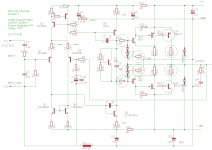
Let's take a closer look at the MX50 SE. The more I looked at it, the more I realized there was nothing really wrong with it, but a couple of changes would give it more power and safer operation. The changes are to add output short circuit protection, and to double the outputs. These changes can be done to the existing board if you are competent and careful.
Below is a schematic of the board as supplied (Warning: may have errors, because this is reverse engineered from the board - the published schematic is intentionally wrong). I show circled mods in the second schematic, doubled outputs and short protection. This has not been verified in actual boards, so beware, but the diodes should work, I'm just not sure about the VI limiting resistors 10k. I also change the emitter resistors to 22.1 ohm and change a resistor in the filter net to 100k, minor tweaks that are easy on an unbuilt kit. You'll want to match the input transistors, pick the closest two in the kit. This amp is missing an output inductor, which you should add too. I will replace the inductor in the ground circuit with a 10 ohm resistor.
To do these mods, you must be good at cutting traces and drilling holes in PCBs. Otherwise, just buy the L12-2, which has the doubled outputs (but no short protection). I really think my speakers deserve the protection, so I add it. That's an easy decision. What's the cost of 4 diodes and 4 resistors, compared to the cost of fried speakers?
I want to do other mods, as follows: change the VAS to a Darlington, change the pre-drivers to MJE 340/350, change a couple of resistor values. None of these are as important as adding short protection, so that's first.
Attachments
Last edited:
Correction: The quad output pair amp is called the L20 V9, not SE. The L20 SE is a dual output pair amp using upgraded higher power transistors with the same output power but lower cost than the L20 V9. To further confuse, there is an L20 V7 around, an older version of the current L20 V9, and there is a red board clone of the L20 V9 by another vendor, YUANJING. So there are 4 L20 variants, in addition to the LJM L20D which is a totally different creature, a digital amp.
Correction: The quad output pair amp is called the L20 V9, not SE. The L20 SE is a dual output pair amp using upgraded higher power transistors with the same output power but lower cost than the L20 V9. To further confuse, there is an L20 V7 around, an older version of the current L20 V9, and there is a red board clone of the L20 V9 by another vendor, YUANJING. So there are 4 L20 variants, in addition to the LJM L20D which is a totally different creature, a digital amp.
Another Correction: Apparently nobody noticed, but the 2-1N4004 diodes on the right are shown incorrectly, they should be reversed. As I said, there may be errors in my reverse engineered schematic, and yep...
In basic form, the schematics shown here are largely a CFP form of Self's Blameless topology. That doesn't mean it works as well or that the boostrap and extra tweaks don't do something interesting and useful to make it unique, better sounding etc.
Consider the kits from a cost point of view. Even a single Signal Transfer Company PCB for the compact Blameless model amplifier will cost several times the price of a pair these kits so you have a very cheap start to some serious learning about amplifier design and performance. I like LJM's reliable designs and resulting sound at whatever level he contributes to the basic form. They have to be based on someone else's design, just like most Forum contributions, because that really can't be avoided if you want low cost, high quality sound kits using generic parts.
I'd take these on as a project too if i didn't have too many already 😀
Last edited:
Note that SSM2220P fits in the existing input transistor holes for this board pretty well. My offsets are now -9mV and -6.8mV.
Another important upgrade IMO is balanced inputs. Otherwise, I got a ton of hum when connected to the PC. I used tiny Beyer Dynamic input transformers from Ebay.
I have used this amp *daily* with 2 old Jensen P12-Q's as low frequency reinforcement for TV and music. I play guitar through it so I can get reverb. I turn it on in the morning and turn if off before I go to bed. I use the hell out of this amp for 1.5 years and so far so good. I think the supply is 24V maybe. It all fit pretty nicely in an old gutted Biamp CPA130 enclosure.
More about my specific build with lots of pics here:
Bridging w/ Input Transformers?
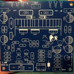
Hi, I just put together one of these kits, so I thought I would share my results so far.
I have attached a picture of the PCB I have for reference. I don't know if there are different revisions, but I think there might be.
I ordered the unassembled kit, and measured all components before soldering. Results were surprisingly good, as all components were were close to PCB values, and showed tight tolerances. So I even used the included caps (for now at least), as they measured well, both on Q, ESR and C values.
Referring to the schematic drawn up by slowhands (thank you), and posted above in thread, in my kit R5 and R14 are not 47 but 100. Also, note that my emitter resistors are 0.1R and not 0.22. Otherwise it seems to match up.
To cut to the chase, in objective bench testing, it actually works really well so far!
DC offset: 0>1mV
THD as measured on HP 339A at 1w 8 ohm level. 100mV input:
1 Khz sine: 0.02% (Class B crossover distortion visible here)
20 Khz sine: 0.07% (Nice 2nd harmonic THD residual, no crossover distortion visible).
- And mind you, my HP339 is not calibrated, and has a noise floor around 0.007 depending on the frequency. So if you subtract that, the MX50SE is starting to look pretty good - although not quite on par with the (original) Doug Self "Blameless" standard.
Power supply is my bench supply, so nothing fancy.
Gain is x28.2
Bias/Iq: When R12 and R13 are matched, Iq is about 15mA.
I tried swapping the ceramic 0.1R for some nice Dale 0.22R I had, but the THD actually went up a bit (!), even if i tweaked R12/R13 to get higher Iq. Can't explain that, but I swapped the kit 0.1R back in, and the THD dropped back down. Don't look a gift horse in the mouth I guess
Conclusion so far: This kit works fine as is (again, quite surprising given the price).
Attachments
Last edited:
A follow up to my previous post:
I forgot to say, that the test results posted were at +/- 35VDC.
Today I tried using an old Toshiba amp as power supply. This gives 40V idle, sagging to 35-36V under load.
With 40V supply, the Iq (bias) was 21-22 mA, and THD dropped down to 0.004% (!), which is about as low as I can measure with the old HP339.
Max power was 63W (in 8 ohm), with THD at 0.04%.
Again, very decent results for such a budget kit.
Of course a Zobel RL output network should be added for real use (silly of LJM not to leave room on the PCB for it), and perhaps some diode protection like slowhands has shown.
I bought this kit as a test, hoping to use them as-is for repair of smaller old amps and active speakers, so not really planning to do any big mods or optimization. But might try replacing the outputs with 2SA1186/2SC2837, and reduce the gain some. Will also test it in 4 ohm load later.
In fact it is a version of Doug Self's Load Invariant Amp (not Blameless) but with only one pair of output transistors. Interesting thing is the way how compensation is done. There are 100R resistors at the base of driver transistors (in addition to standard Miller compensation cap on the VAS transistor). It makes this amp bullet proof against oscillation. Very stable. Output inductor would require more space on the pcb so you can add it on the loudspeaker terminals. MX50 SE is the champ of affordable DIY power amp class.
There is one LJM amp kit that is often overlooked which I recently bought. It's MX100 V9. The kit uses latest edition of Toshiba's 5200/1943 output pair (TT edition) and great Toshiba's 1930/5171 drivers. All are originals. Amazing. It's stereo kit that has two channels of (a somewhat simplified) MX 50 SE with PSU and relay protection on the single pcb. Price is around 40 dollars but keep in mind that it is stereo kit with PSU and protection. This is ninth version of this kit so it passed through long process of refinement and upgrading. Relay protection uses main voltage rail so only thing that you need is 25-0-25V mains transformer, some input and output connectors and suitable enclosure for a high quality power amp.
It's so good to have minimum wiring in the amp! Another great kit from LJM's lab.
It's so good to have minimum wiring in the amp! Another great kit from LJM's lab.
With regard to your measurements, using the MX50.. at lower supplyrail voltages would probably call for using a trimmer to set the outputstage to the proper bias-current and then repeat the distortion measurements.With 40V supply, the Iq (bias) was 21-22 mA, and THD dropped down to 0.004% (!), which is about as low as I can measure with the old HP339.
Max power was 63W (in 8 ohm), with THD at 0.04%.
Will also test it in 4 ohm load later.
Loaded with 4 Ohms the amp might well survive under musical reproduction, but I don't think it was intended for such low impedance loads.
Some time ago I did several simulation-runs on the original MX50 with intentional low impedance down to 2 Ohms. My objective was to verify if the SOAR of the output transistors was not exceeded. Those runs indicated that this amp is absolutely 8 Ohms stable. Testing for 4 Ohms stability asked for lowering the rails voltage. 2 Ohms stability was never met...
For the stability test-runs I assumed the actual impedance at 3/4 (resistive) of the specified number, because loudspeakers usually behave in that way. So 8 Ohms became 6 Ohms and so on. The amp was crancked up to full power and I measured the current through the devices. This testing method (worst case loading) does not represent the amp's performance in musical reproduction.
The SOAR of the MX50SE's output devices might differ a bit from those in the MX50's.
Lower value resistors have lower noise. I think that is why amps often have 10-20K input impedance - but there might be other reasons also.
About 100K I think, but you can lower it if you want, as shown earlier in this thread.
Why would you want to lower the input impedance?
The input impedance setting resistor Rin is only seen as an input when the interconnect is disconnected.Lower value resistors have lower noise. I think that is why amps often have 10-20K input impedance - but there might be other reasons also.
Rin in see as a parallel resistor to the Source impedance. This can be anywhere from 10r to 2k
It's the source impedance that dominates the resistor noise imported into the amplifier input.
If one has an RF attenuating resistor in series with the input then that adds to the source impedance. Fortunately that filtering resistor feeds into a capacitor and the capacitor presents a falling impedance with rising frequency that is also in parallel with the other resistors at the input.
I started another thread about replacing the STK8050s on a technics SU-V4 a friend really wants to save.

As these stks are notorious for being faked and not very reliable to begin with I looked for a different option and went for the mx50se kits and that brought me here. They work fine with the present supply rails (48v which drops down to 46 under load). and the amp has it's build in protection circuit so that's good. The thing is that the su-v4 doesn't have an actual preamp stage and has the tone controls added to the negative feedback loop which also adds some gain (a good thing because straight from a source this circuit doesn't amplify the signal enough). I take my signal directly from R302, signal ground comes from the other side of R304, the second ground connection goes to the ground connection between the two filter caps and output goes to L302 (I disconnected R348 because that part is already on the mx50 board). Also before the left emitter resistor I connected to TP302 that goes to the overload detection circuit. For now I didn't include the tone controls (that will be connected between R27 and R18 (on the schematic slowhands posted). The thing is, I have hum, 100hz . I can hear it through headphones ever so slightly but adding the tone controls adds gain to the circuit the hum gets amplified and becomes quite loud. When I turn the volume up the 100hz hum goes away but a higher frequency noise appears. With little surprise adding filter capacitance doesn't change anything, I tried twisted wires for the signal input, shielded with only one end connected and tried moving the wiring but nothing changes anything 🙁.
As these stks are notorious for being faked and not very reliable to begin with I looked for a different option and went for the mx50se kits and that brought me here. They work fine with the present supply rails (48v which drops down to 46 under load). and the amp has it's build in protection circuit so that's good. The thing is that the su-v4 doesn't have an actual preamp stage and has the tone controls added to the negative feedback loop which also adds some gain (a good thing because straight from a source this circuit doesn't amplify the signal enough). I take my signal directly from R302, signal ground comes from the other side of R304, the second ground connection goes to the ground connection between the two filter caps and output goes to L302 (I disconnected R348 because that part is already on the mx50 board). Also before the left emitter resistor I connected to TP302 that goes to the overload detection circuit. For now I didn't include the tone controls (that will be connected between R27 and R18 (on the schematic slowhands posted). The thing is, I have hum, 100hz
. I can hear it through headphones ever so slightly but adding the tone controls adds gain to the circuit the hum gets amplified and becomes quite loud. When I turn the volume up the 100hz hum goes away but a higher frequency noise appears. With little surprise adding filter capacitance doesn't change anything, I tried twisted wires for the signal input, shielded with only one end connected and tried moving the wiring but nothing changes anything 🙁.- Home
- Amplifiers
- Solid State
- MX50SE LJM 2015