Power supply noise could be introduced in very many ways as no doubt, you already know. Generally, an amplifier of this age will have electrolytic cap problems and these usually show up as 100Hz hum - maybe not so bad in the original form yet but now that you are making deep changes, it may be more obvious.
I have to admit that that I don't understand how you can retrofit a standard type of class AB amplifier here, where the original amplifier design is a "New class A" type, unique to Technics and modified to accommodate tone controls in the feedback network. I'd need to see full schematic of the changes to begin to see what the issues are.
Id rather not mess with the power amplifier's stability arrangement by going down this path. I'd simply pull all the amplifier and tone control sections, starting from scratch by rebuilding with a basic class AB design power amp. such as you have and adding conventional baxandall tone control circuits in a new preamp section preceding it. If the required control pots don't match the existing ones, you can always substitute those with the right value, good quality types.
The resulting amplifier may only resemble the original in appearance but once you install an entirely different design power amp, there's little left in there worth preserving anyway.
Hello Ian,
This amp is from a friend and the caps have already been replaced (I checked values and polarity just to be sure but that's all fine).
I did exactly that, I removed everything after the volume control and took my signal and ground input from there. For now tone controls aren't connected so ignore R27 (it is still in its original place on the mx50 board.

Adding the tone controls doesn't change the stability of the amplifier from what I can see, it simply adds gain and amplifies the hum I'm already seeing without them. To recap, the only things connected to the original su-v4 circuit are signal in, signal ground in, ground in, + and - supply rails and output.
This amp is from a friend and the caps have already been replaced (I checked values and polarity just to be sure but that's all fine).
I did exactly that, I removed everything after the volume control and took my signal and ground input from there. For now tone controls aren't connected so ignore R27 (it is still in its original place on the mx50 board.
Adding the tone controls doesn't change the stability of the amplifier from what I can see, it simply adds gain and amplifies the hum I'm already seeing without them. To recap, the only things connected to the original su-v4 circuit are signal in, signal ground in, ground in, + and - supply rails and output.
OK, that's not a problem then. I read it as you were keeping the tone control arrangement located in the SUV4 amplifier feedback loop. That definitely would require a careful match to the amplifier because of how the loop affects the amplifier's Nyquist stability.
A preamp with tone, volume, balance etc. controls located before the amplifier can be considered as another device, provided it's signal grounding remains isolated from the chassis except for one ground point only and ground itself remains intact from input through to the power amplifier output. That condition is for safety and to avoid forming signal ground loops which impose mains (50Hz) hum on the signal. 100Hz hum is generated in the power supply and could even be caused by old caps or more likely, incorrect separation of star earthing for the amplifier and/or preamp power supplies.
You can test for the location of mains grounding faults by changing the input signal ground connection to the power amplifier to star ground but be cautious with safety - ungrounded equipment is unsafe and should your mains supply be from an ungrounded plug, you don't even have that protection.
Rod Elliott's (ESP) design guidelines on grounding can be helpful but you will need to read a lot to find to find details applying to all types of arrangements.
Well that was the goal actually, I tried it and it definitely works. The only thing is that as I have some hum it gets really loud with the tone controls inserted (those add about 20db of gain). But for now I left them out again to concentrate on finding the origin of the hum.
Before the power amp there are the loudness, high filter, low filter, balance and volume (I must add that activating the low cut filter changes the hum to a higher frequency). Ground works its way from chassis at the input rca all the way to the input of the power amp, the output has takes its ground connection from the power supply ground between the two filter caps and then directly to chassis next to the heat sink. As you can see on the schematic there really is just one power supply, the unregulated part feeding the outputs is then being regulated and fed to the riaa circuit and IC303. As I said caps are new.
Connecting signal ground in to the power amplifier ground makes things a lot worse. I find this not really surprising unless I understood you wrong, you did mean to connect the "gnd in" next to the signal input on the mx50 board, to the power amplifier ground (in the case between the two filter caps) ? Also the mx50 has 2 ground terminals, signal in ground and a ground terminal for the rest of the circuit, filtering and zobel network. They are connected through an inductor.
Last edited:
MX50SE bias settings
Can't remember what thread I wrote in before about these amps, but they are my current low budget favorites for giving accurate bass (best with 8ohm). Mid and treble sound ok, but my new 'reference' there is the JLH 1969 amp.
Anyway, I did some bias adjustment watching distortion spectrum that I thought I would share. I noticed some major difference between transistors. Seems like the KEC transistors need about 9-10mV over the 0,15ohm emitter resistors to have a nice distortion spectrum, and the Sanken (copies?) are fine with abt 4mV. For other transistors not delivered with the kit, I also tried with some Sankens 'recycled' from a Yamaha receiver, and those seemed to be happiest around 7-8mV. I have also tried some Toshibas (with really linear hfe/current) but did not set the bias watching distortion spectrum with those.
How I tested it: Arta and soundcard, dual sine input(mainly), mostly 4ohm load, but double checked 8ohm too, varied amplitudes, around normal listening levels of a few volts.
fuses on the power supply
I would like to add fuses on the power supply branches but I don't know what value (in amper) to insert. can someone help me or tell me how to perform the calculation for the current that the fuses must support?
I would like to add fuses on the power supply branches but I don't know what value (in amper) to insert. can someone help me or tell me how to perform the calculation for the current that the fuses must support?
Help on blameless
Dear Sir,
Did you complete the modifications ?
Thanks,
Sumesh
Dear Sir,
Did you complete the modifications ?
Thanks,
Sumesh
This amp is a clone of Douglas Self's "Blameless Amp", with CFP outputs (Self uses EF). The design is published in Self's many books and articles. The front end is an almost exact copy including passive component values. Compared to EF outputs, the CFP output stage is excellent because it gives lower distortion and lower bias current for cool running. So, overall this amp sounds good, is simple, cheap and tiny, and for price is hard to beat.
It has limits, imposed by its low cost. It is rated 50 Watts output at +-45VDC supply, which it delivers, but that's the max. These limits should not be exceeded for several reasons. First, the electrolytic capacitors are rated 50v, and they will eventually leak, bulge or explode if used at higher voltages. Second, the 1815 transistors are rated for 50v Vceo, and must be used below this rating or they may fail. Third, the output transistors are already outside their safe operating area and can fail if driven hard into low impedance or reactive loads. So the 45 volt supply limit is very real and should be followed. For 4 ohm loads, you must lower the power supply voltage or you will burn out the output transistors.
You can beef this up to get a little more power, but it's risky. You can replace the 50 volt capacitors with 63v, and change the 1815 transistors to higher voltage parts which will have different pinouts. But it's risky, because the output stage is already at risk for exceeding safe operating area and failing in second breakdown, especially with low impedance reactive loads like most real world speakers. Rather than tweaking this design, you can find better starting points for almost the same price.
This designer, LJM, has a family of good kit amp designs sold by many Chinese dealers on ebay and elsewhere. This model, the MX50 SE, is fine up to 50 watts. The next step, LJM's L12-2, is a better choice up to 100 watts. It has essentially the same front end but doubled output transistor pairs and uprated capacitors, so it's OK for higher power. For even more power, LJM's L20 SE gives 200 watts. The L20 SE has quadrupled output transistor pairs and MOSFET drivers, but the front end is essentially the same. LJM has other amps of different design (some digital, some MOSFET) but here I am focusing on these three designs which are very similar in design but have a range of outputs.
Once again, all of these designs are clones of Self's Blameless Amp, which is an excellent starting point. Performance is good, cost is low, and the boards and parts are of surprisingly high quality. I could not buy the individual components and build these for such a low price. Only in China... I'm impressed. But of course I could not resist the urge to tweak a little.
Let's take a closer look at the MX50 SE. The more I looked at it, the more I realized there was nothing really wrong with it, but a couple of changes would give it more power and safer operation. The changes are to add output short circuit protection, and to double the outputs. These changes can be done to the existing board if you are competent and careful.
Below is a schematic of the board as supplied (Warning: may have errors, because this is reverse engineered from the board - the published schematic is intentionally wrong). I show circled mods in the second schematic, doubled outputs and short protection. This has not been verified in actual boards, so beware, but the diodes should work, I'm just not sure about the VI limiting resistors 10k. I also change the emitter resistors to 22.1 ohm and change a resistor in the filter net to 100k, minor tweaks that are easy on an unbuilt kit. You'll want to match the input transistors, pick the closest two in the kit. This amp is missing an output inductor, which you should add too. I will replace the inductor in the ground circuit with a 10 ohm resistor.
To do these mods, you must be good at cutting traces and drilling holes in PCBs. Otherwise, just buy the L12-2, which has the doubled outputs (but no short protection). I really think my speakers deserve the protection, so I add it. That's an easy decision. What's the cost of 4 diodes and 4 resistors, compared to the cost of fried speakers?
I want to do other mods, as follows: change the VAS to a Darlington, change the pre-drivers to MJE 340/350, change a couple of resistor values. None of these are as important as adding short protection, so that's first.
Folks, re. bias: following assembly of two of these I notice one runs quite bit hotter that the other, also when idling. Anyone experienced of thermal runaway of these amps?
PS - thanks to JVHB for suggesting 4uH//10ohm in series with output - good advice - my earlier Velleman100 literally went up in flames when connected to a difficult speaker... MX50E is fine with it..
PS - thanks to JVHB for suggesting 4uH//10ohm in series with output - good advice - my earlier Velleman100 literally went up in flames when connected to a difficult speaker... MX50E is fine with it..
Folks, re. bias: following assembly of two of these I notice one runs quite bit hotter that the other, also when idling. Anyone experienced of thermal runaway of these amps?
PS - thanks to JVHB for suggesting 4uH//10ohm in series with output - good advice - my earlier Velleman100 literally went up in flames when connected to a difficult speaker... MX50E is fine with it..
Have you checked for oscillation?
Also - I think that 4uH is a bit high for the output inductor. I would use 2uH or 2.2uH and also reduce the resistor to 4 ohms or so.
Is it running hot with or without a load connected?
What are the voltages across Base / Emitter on both output transistors?
Are these voltages the same on both amps?
Also - I edited my post - did you see my comment about the output inductor?
Self recommends about 2.2uH for most of his amps. (10 turns on a 25mm former)
What are the voltages across Base / Emitter on both output transistors?
Are these voltages the same on both amps?
Also - I edited my post - did you see my comment about the output inductor?
Self recommends about 2.2uH for most of his amps. (10 turns on a 25mm former)
Thanks audio_tony for the voltage tips - I will check those and also voltage across emitter resistors - they are probably different due to different bias currents - but the original questions was if anyone has experienced thermal runaway? If not, I am not to worried about a bit too high bias current. Re. the coil - you mean coil has 25 mm diameter?
I've not had any issues with thermal runaway.
In his book, Self recommends 10 turns on a 25mm former - so yes, the coil should be 25mm in diameter.
Take a look at the coil on his trimodal amp here
The Signal Transfer Company: Trimodal Power Amplifier
Can you post a picture of the modules you have?
In his book, Self recommends 10 turns on a 25mm former - so yes, the coil should be 25mm in diameter.
Take a look at the coil on his trimodal amp here
The Signal Transfer Company: Trimodal Power Amplifier
Can you post a picture of the modules you have?
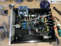
That's a nice chassis - you've done a good job there.
I had those same Velleman modules (they were based on a 90's Elektor design - "70 to 100 watt amplifier")
I thought the Velleman modules sounded better than the MX50 lol
I note you are using an SMPS - I wonder if this is causing the MX50 to run warm?
My MX50s are cold when idle.
Have you checked the PSU line for noise?
Maybe you need some additional PSU decoupling close to the boards.
Thanks! - Here is a photo of one of the rails, 200 mv PP 50hz, not much SMPS HF - should be OK? At full load voltage drops 3v with music peaks...
But I have the reason for one of them running hot - bias current results in 35 mv over the 0.22 ohm, while the other has only 3 mv. I used a Q7 669 from my stock rather than the one supplied with the kit - maybe the reason... so change transistor (tricky with this PCB) or adjust bias..
But I have the reason for one of them running hot - bias current results in 35 mv over the 0.22 ohm, while the other has only 3 mv. I used a Q7 669 from my stock rather than the one supplied with the kit - maybe the reason... so change transistor (tricky with this PCB) or adjust bias..
Attachments
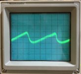
There could be some HF superimposed in that ripple. (the waveform looks a little noisy, unless it's your scope).
Ideally you need to run it through a high pass filter and then if there's any HF ripple.
The 50Hz ripple is low enough though.
I would also replace / fit the correct transistor as that could be causing you issues too.
Ideally you need to run it through a high pass filter and then if there's any HF ripple.
The 50Hz ripple is low enough though.
I would also replace / fit the correct transistor as that could be causing you issues too.
Yup, changing the Q7 669 to the one with the same number from the kit helped, odd. Bias now ok. Not sure what to do about the HF on the rails, maybe some 100 nF to earth. I am not totally impressed with distortion on this amp, runs around 0.02%, rising to 0.1% at high frequency.
- Home
- Amplifiers
- Solid State
- MX50SE LJM 2015