Will do.. I am putting 2k multi turn pots to replace r13 so I will adjust. I cant remember if I adjusted bias looking at notch distortion with a scope or just a multimeter across the collectors of q12, q14...
My DAC has balanced output. Could one run this input stage balanced with the negative through R18? (R18 and R27 must then be increased by around 33x)
The THD on my MX50 is 0.0062% @1w / 1kHz and 0.0038% @ 44w / 1kHz
Mine is running 38-0-38 DC rails.
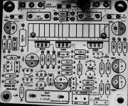
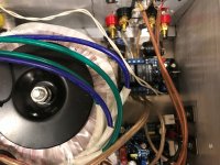
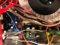
I have attached pics of my amp board so you can compare.
I've just built a pair of the MX50SE and going to put 2SC500 and 2SA1943 in them. My question is I'm going to use a 250va 30-0-30 toroid with 35 amp bridge and a couple of elna audio 10000uf 63 volt caps for filtering. This should give +-42vdc rails. I've been told not to use this much voltage... I will be adding the inductor/resistor network on the output and feeding 8ohm floor speakers.
Do you think this is a no go with 42vdc rails?
Hi, 42V rails is generally too much for a single pair of BJT outputs, especially when the amp circuit has no integrated overload protection. You risk frying your outputs due to SOA (safe operating area) limitations. See relevant datasheets for details...
But with 8 ohm speakers, it will work just fine and nothing bad will happen at low and moderate output levels. Just be aware that if you "crank it to 11", the outputs will likely/perhaps not survive for long.
But with 8 ohm speakers, it will work just fine and nothing bad will happen at low and moderate output levels. Just be aware that if you "crank it to 11", the outputs will likely/perhaps not survive for long.
Last edited:
...But it also depends on the specific transformer and how much the voltage drops under load.
If eg. you used a 1000VA toroid the rails would be very stiff, and only have a slight drop under a 200w load. But with a smaller transformer, there can be a significant drop:
I have benchtested an MX50SE board using an old transformer (no specs, but probably less than 150VA) which gave 40V rails with no load.
Into an 8ohm load, the amp could deliver 22.5Vrms (=63W) before clipping.
At this point the rails had sagged to app. 36V, so a drop of 4v from idle state (also due to increased voltage drop in rectifier).
I would personally consider this setup quite safe for 6-8 ohm speakers, but not for 4 ohm.
In your case, the rail voltage might be 42V as you write (30x1.414=42.42), but your actual rails will be less due to rectifier diode losses - perhaps around 41V idle. And under load, it will likely drop below 40V, but you will have to test with a dummy load to find out.
Last edited:
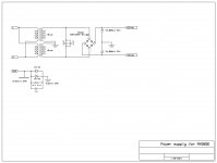
I've decided to power this using an Antek AS-4218. 18-0-18 400VA with a 35A full wave bridge and 10000uf/35v caps. I've replaced the 50v 100uf's with 470uf/35v at C5 and C14. Also changed the 100uf/50v to 100uf/35v at C2,4,7. It will have two 2SC2837's and two 2SA1186's on each channel.
I have one question and hope someone can answer...
C3... 470uf/16, should this be replaced with 1000uf/6.3v? And why? Thought I read that it will give it a stronger lower frequency range, but I can't remember.
What a project!! Ugh!
I have one question and hope someone can answer...
C3... 470uf/16, should this be replaced with 1000uf/6.3v? And why? Thought I read that it will give it a stronger lower frequency range, but I can't remember.
What a project!! Ugh!
Attachments
I think it's like this: For improved LF, the first you should do is to increase the input cap, if that's not enough, you can try the feedback cap. Input cap 10u or so.
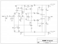
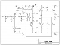
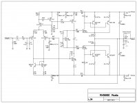
MX50SE board mods
After reading all the threads on the MX50 and MX50SE (more than once) and gathering info for improvements, I decided to try and put it all together. Before I finalize the install of all this into a chassis I wanted to make sure I wasn't missing anything and possibly get more opinions, suggestions from experienced people on this forum.
1. Was told to try and use +-25vdc on the rails. K, got it.
2. Purchased a AS-4218 400VA 18V - 0 - 18V Toroid.
3. Purchased a KBPC3504 35amp Full wave bride.
4. Purchased two 10,000uf/35v audio grade caps from mouser
5. So with 25v rails I can use 35v capacitors on the board which allows
470uf/35v cans to fit on the board.
Plus, correct me if I'm wrong, Caps should be at about 80% of the voltage
to function correctly at the rated uf.
6. Replace the 470uf/16v cap with 1000uf/6.3v. Does it have to be NP?
7. Replace R13 (1k) with a 2k multi turn pot.
8. Created two 1.5uH air inductors for the out-puts and 2 ohm 2w resistors
paralleled with them.
9. Purchased a Gump's grocery Speaker Protection Board from Amazon.
10. Purchased four of 2sa1186 and four 2sc2343 from Digi-Key. All have case
code Y.
11. Purchased four 5watt 0.2 ohm for adding the extra pair of final transistors.
12. When adjusting bias for this configuration, I guess I could do the notch
distortion method but then of course check the voltage across the
collector resistors.
Am I missing anything?
I am not planning for an auditorium sound system just something that sounds excellent.
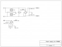
I've attached the stock and modified .SCH that can be edited using ExpressSCH. It's a free download program. I had to change these to a .txt file so you have to change the extension back to .sch after you download it
After reading all the threads on the MX50 and MX50SE (more than once) and gathering info for improvements, I decided to try and put it all together. Before I finalize the install of all this into a chassis I wanted to make sure I wasn't missing anything and possibly get more opinions, suggestions from experienced people on this forum.
1. Was told to try and use +-25vdc on the rails. K, got it.
2. Purchased a AS-4218 400VA 18V - 0 - 18V Toroid.
3. Purchased a KBPC3504 35amp Full wave bride.
4. Purchased two 10,000uf/35v audio grade caps from mouser
5. So with 25v rails I can use 35v capacitors on the board which allows
470uf/35v cans to fit on the board.
Plus, correct me if I'm wrong, Caps should be at about 80% of the voltage
to function correctly at the rated uf.
6. Replace the 470uf/16v cap with 1000uf/6.3v. Does it have to be NP?
7. Replace R13 (1k) with a 2k multi turn pot.
8. Created two 1.5uH air inductors for the out-puts and 2 ohm 2w resistors
paralleled with them.
9. Purchased a Gump's grocery Speaker Protection Board from Amazon.
10. Purchased four of 2sa1186 and four 2sc2343 from Digi-Key. All have case
code Y.
11. Purchased four 5watt 0.2 ohm for adding the extra pair of final transistors.
12. When adjusting bias for this configuration, I guess I could do the notch
distortion method but then of course check the voltage across the
collector resistors.
Am I missing anything?
I am not planning for an auditorium sound system just something that sounds excellent.
I've attached the stock and modified .SCH that can be edited using ExpressSCH. It's a free download program. I had to change these to a .txt file so you have to change the extension back to .sch after you download it
Attachments


Dear all,
I have simulated this amplifier with many other output transistors than 1047/817, I cannot find spice models. In all scenarios I obtain a very low distorsion (with bias adjusted to 10 mV across R15/R25 as per last schematics posted).
With R19/R21 =100 ohm I have an offset =7mV.
Is this something to worry about?
Changing R19/21 values to 10 ohm, offset: 2 mV. Any concern about this change?
I will use 2 K Ohm trimmers to better bias adjustment.
Thanks .
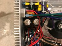
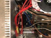
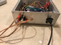
As far as I'm going with it...
I know, I know, the chassis is very small. Originally I was building a 2.1 system but it didn't work out so well. So I decided to cram all this stuff into this chassis I already built It does work very well though. No hiss or hum, stays cold and plays plenty loud!
I need to look at the bias though as I think it needs more than 7mv, I do have double the outputs. I am using 18-0-18 300va and a pair of 10000uf 35v for filtering. I'm then feeding +-25 vdc to a regulator board to drop it to +-15 for the preamp.
Fun project and the next one will have a Larger Chassis with analog VU meters!
Thanks for all the info, mods and advice on this kit. 😎
I know, I know, the chassis is very small. Originally I was building a 2.1 system but it didn't work out so well. So I decided to cram all this stuff into this chassis I already built
It does work very well though. No hiss or hum, stays cold and plays plenty loud! I need to look at the bias though as I think it needs more than 7mv, I do have double the outputs. I am using 18-0-18 300va and a pair of 10000uf 35v for filtering. I'm then feeding +-25 vdc to a regulator board to drop it to +-15 for the preamp.
Fun project and the next one will have a Larger Chassis with analog VU meters!
Thanks for all the info, mods and advice on this kit. 😎
Attachments
-
 IMG_1070.jpg715.9 KB · Views: 299
 -
 IMG_1069.jpg728.6 KB · Views: 284
 -
 IMG_1068.jpg659.4 KB · Views: 273
 -
 IMG_1067.jpg699.6 KB · Views: 406
 -
 IMG_1066.jpg722.1 KB · Views: 406
 -
 IMG_1065.jpg742.2 KB · Views: 417
 -
 IMG_1064.jpg800.1 KB · Views: 438
 -
 IMG_1063.jpg902.7 KB · Views: 434
 -
 IMG_1071.jpg682.1 KB · Views: 277
All... I originally set the bias for 7mv and it sounded a little bad...distorted so I set bias for 14mv and it's night and day sound difference. Maybe because I've double the outputs is the reason for a higher bias voltage needed. I've had it playing at a decent volume for an hour or so and it just gets luke warm.
DC offset... Left channel=0.008, Right channel=0.000
With 1000hz input tone and output into an 8ohm dummy load, it clips at around 15.5 vrms. Not much power when you do the math. I think with a higher voltage transformer this would increase. All in All the sound Q is great.
Now to build an L20SE set. This will have +-43 vdc.
- Home
- Amplifiers
- Solid State
- MX50SE LJM 2015