I have a quick Arduino code class question. Should these longs be unsigned? What happens when millis rolls over to a negative value?
Jeff, you're absolutely right - that's why we've got
unsigned long currentMillis = 0;
later in the listing.
This is the only variable, where it counts and rolls over. Those definitions in the beginning are just the values to compare with.
Thank you. That really helps when there are changes that need to be tracked.
I've been doing most of the revisions to Valery's initial board. This makes it tough for changes to the first post. This wasn't an issue until recently, when more members have started trying these boards out. To aggravate the situation, I try new designs with every amplifier build I do, looking for improvement.
A build thread might be in order. This thread is great for accumulating suggestions and info.
Last edited:
Jeff, you're absolutely right - that's why we've got
unsigned long currentMillis = 0;
later in the listing.
This is the only variable, where it counts and rolls over. Those definitions in the beginning are just the values to compare with.
Thanks. I'm starting to figure this stuff out.

I've been doing most of the revisions to Valery's initial board. This makes it tough for changes to the first post. This wasn't an issue until recently, when more members have started trying these boards out. To aggravate the situation, I try new designs with every amplifier build I do, looking for improvement.
A build thread might be in order. This thread is great for accumulating suggestions and info.
My idea was to consider, say, your revision V3.5 of the board as a stable finished one, together with v06 firmware. And then we will just update the links index, pointing to the later improvements.
My idea was to consider, say, your revision V3.5 of the board as a stable finished one, together with v06 firmware. And then we will just update the links index, pointing to the later improvements.
That's probably a good idea. 3.6 is actually the same thing with corrected silkscreen, but I think Quan has been the only person to build that one.
Any newer designs are going to require updated software to operate so It's likely best to start another thread and keep it separate.
This is the one I use. 110-43-314-41-001000 Mill-Max | Mouser
It deforms the pins of the IC, so don't fully seat the IC until you are sure you are happy with the programming.
Is this part no. For 28pin version?
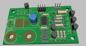
I've come up with an optically isolated DC detection circuit that still retains all the functionality of the last design. As tested in breadboard, detection is activated at + or - 1.25 VDC. As of yet it is untested for false detection on AC signal. It still activates on loss of rail supplies and still interfaces with the main control board the same way as the last design as well. Any suggestions on improvement are welcome before I order some test boards.
Attachments
Why not test it to see how well it rejects audio(ac) information? It basically comes down the the response of the filter. I assume you are using bi-polar ecaps in the 220-330uF range as everyone else does.As of yet it is untested for false detection on AC signal.
I just wired up an old Hitachi HA12002, since I had one on hand as it was used in the old Sansui G-7500. This is the protection circuit for my 120W/ch amp, I used 68K/220uF. Seems to be working fine. For 200W/channel increase R to the 75K range.
If you have a sig gen like a hp 3325A you have it all in one box, ac and dc offset capabilities. Btw I bought one of thse lately, what a deal for $200cdn!! lots of great finds these days.
I plan to test with AC signal when I'm back at the office next. I was too tired to test last night after I got it up and running (I've got health issues keeping me from sleeping properly). My test equipment is junk, but I have a signal generator that will work.
This is a modified version of the ESP design. They recommend 47uF maximum for reaction speed. I'll know more after some more testing. I'd like to figure out a little more elegant way to reduce voltage for the opto-isolator yet. I would prefer not to run a 3 watt resistor and zener for something like this.
This is a modified version of the ESP design. They recommend 47uF maximum for reaction speed. I'll know more after some more testing. I'd like to figure out a little more elegant way to reduce voltage for the opto-isolator yet. I would prefer not to run a 3 watt resistor and zener for something like this.
Yes maybe you are correct use two 100uF back to back polarized ecaps as Doug Self does too. We are talking msecs here.
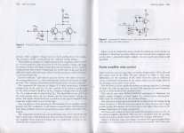
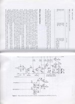
I have not looked at the circuit, but if i am correct you are using the 3W resistor because you are using the opto as the DCV sensing device. If it is isolation you want then sure use the opto, but not as the detector, use the traditional transistor circuit to drive the opto instead. See the attached, you can use ckt fig4 or fig5, put your opto in series with r9 and select r9 for your required opto led current.
I have not looked at the circuit, but if i am correct you are using the 3W resistor because you are using the opto as the DCV sensing device. If it is isolation you want then sure use the opto, but not as the detector, use the traditional transistor circuit to drive the opto instead. See the attached, you can use ckt fig4 or fig5, put your opto in series with r9 and select r9 for your required opto led current.
Attachments
Output current sensing: My textbook recommends using a Hall device for accurate DC current measurements, and using inductive technologies like a transformer for accurate AC current measurements. Hall Effect device vs. constructing a transformer from the (typical) 1.5uH output stability inductor which is used to balance capacitive loads.
Instead of the traditional wrapping an inductive wire coil around a small value resistor, has anyone wrapped the output protection inductor around a toroid core and added a secondary winding for AC output current sensing? Works correctly in LTSpice sims, but cannot sense DC current. But hey.... I have a <1mV opamp based DC servo for that.
Instead of the traditional wrapping an inductive wire coil around a small value resistor, has anyone wrapped the output protection inductor around a toroid core and added a secondary winding for AC output current sensing? Works correctly in LTSpice sims, but cannot sense DC current. But hey.... I have a <1mV opamp based DC servo for that.
- Status
- This old topic is closed. If you want to reopen this topic, contact a moderator using the "Report Post" button.
- Home
- Amplifiers
- Solid State
- How to build a 21st century protection board