Because Early Voltage does not exist on datasheet, I will appreciate if someone make measurement of Early Voltage of popular VAS transistor.
I will like to see Early Voltage on TO92 or similar for low power amplifier, TO126 or similar for medium power amplifier, and TO220 or similar for high power amplifier.
I didn't see baxandall super pair for VAS in this book. Why?
I will like to see Early Voltage on TO92 or similar for low power amplifier, TO126 or similar for medium power amplifier, and TO220 or similar for high power amplifier.
I didn't see baxandall super pair for VAS in this book. Why?
Last edited:
Most transistor data sheets DO show early voltage but not as a single number.
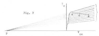
Look at the output graph, where the lines are slowly rising going to the right. If you extend these lines back to the left, until they cross the X-axis at P, that's the early voltage. No need for any measurements.
You will typically see that all back-wards-extended lines in the graph bundle cross the X-axis at the same point.
I give you an example, hand drawn by the great Peter Baxandall, just for you")
Jan
Look at the output graph, where the lines are slowly rising going to the right. If you extend these lines back to the left, until they cross the X-axis at P, that's the early voltage. No need for any measurements.
You will typically see that all back-wards-extended lines in the graph bundle cross the X-axis at the same point.
I give you an example, hand drawn by the great Peter Baxandall, just for you
Jan
Attachments
That is because it has all sorts of drawbacks, as described, a major one being that it needs a push-pull VAS, which as Chapter 8 shows is not a good way to go.
I'd be glad to hear your thoughts on the push-pull VAS issue- it seems to me that Chapter 8 demolishes the whole business. That was not what I was expecting when I started my research; it's a bit disconcerting when the most conventional approach keeps coming out as the best.
There are quite a few designs floating around on this forum that show sub ppm distortion using push pull TIS.
However, unsymmetrical slew rate, unsymmetrical drive are two distinct disadvantages I can think of, so I don't think you can sweep it aside. Ditto CFA.
All these topologies have their pros and cons and that's what should be compared IMV.
Give us facts Doug, and not opinions
Last edited:
There are quite a few ... on this forum that show sub ppm distortion using push pull TIS...
Hi Andrew
Sub PPM at what frequency and power?
Some people make spectacular distortion claims at low frequency, low power.
Usually one or more of - unrealistic models, unrealistic Unity Return Ratio Frequency, unrealistic stability, is used to further inflate the claim.
This inflation tends to undervalue the achievement of people who produce excellent amplifiers with realistic low numbers.
My examples of these excellent amplifiers include those of yourself, Damir (Dadod), Toni (ASTX), (Ostripper) and a few others.
I would really like to discover what is the true state of the art.
Standardized at 20 kHz, as recommended by Bob Cordell, who has achieved sub PPM, even simulation, with realistic assumptions?
I understand that the the actual implementation of sub PPM is a whole new area, hence the comparison between simulations to keep it equal.
The best I know is the Ovidiu/Stuart amp, any others?
Best wishes
David
More on the actual issue of push pull TIS/VAS once I obtain a 6th edition.
Last edited:
Most transistor data sheets DO show early voltage but not as a single number.
Look at the output graph, where the lines are slowly rising going to the right. If you extend these lines back to the left, until they cross the X-axis at P, that's the early voltage. No need for any measurements.
You will typically see that all back-wards-extended lines in the graph bundle cross the X-axis at the same point.
I give you an example, hand drawn by the great Peter Baxandall, just for you
Jan
I know the definition of Early Voltage. But I don't have transistor curve tracer.
Edit:
You mean, I must print the datasheet for IC - VCE graph then draw the line? I will try it.
Last edited:
Self takes a path, does get some perspectives that appear generally useful
Doug's book's circuit variations, AP plots collect lots of "facts"
interpretation is what designers desperately want
but circuit choices, topology, parts influence on "audio quality" aren't some smooth single valued hill climb
simple answers are likely to be non-optimal when implemented in real world complexity
as examples read my "objections"/clarifications in the "CFA Amp" thread - many there appear to be using just this too simple thinking, fanboy attribution of "advantages of CFA" for circuit properties that are not linked to "CFA" topology that intelligent designers have been trading off, find differing balance points for quite a few decades
many of my "refutation" sims in the CFA thread feature Bob's 1983 Mosfet Amp, refer to his paper's measured results
I would of course also like to know what you think is missing, but, as
I say, there is no prospect of a new edition in the foreseeable future.
Hi,
FWIW the meaningless absorption with THD figures near full power,
and lack of analysis of clipping characteristics, and control thereof.
For a 100W per channel amplifier I couldn't care less about the
distortion above 33W or even lower (unless its a basic problem).
How amplifiers deal with mild overload is a rich furrow IMO
not sufficiently documented, for sure some do far better
than others in terms of recovery, and I for one would
have no problem with large amounts of distortion at
nominal full power for a smooth overload characteristic.
rgds, sreten.
Member
Joined 2009
Paid Member
he does not believe that CFA holds any promise for improved performance.
me neither,
actually, I had a bit of a laugh at the threads spawned on this topic - and yet in the end there was not a clear winner (CFA vs VFA). Anyhow that's an old topic now thank goodness.
Most interesting comments about symmetric VAS and even more interesting regarding Class A inefficiency. These both deserve some discussion - but not sure we can have that discussion here without violating Copyright or limiting it to the few book buying contributors.
By the way, I'm a fan, I think Doug's book(s) are great reading.
You mean, I must print the datasheet for IC - VCE graph then draw the line? I will try it.
Yes of course. Just extend a few lines like the top and the bottom one. You don't need any mV accuracy anyway, because the early voltage varies between parts. You want to get in the ballpark.
With some care you can just do it by eye!
Jan
Thanks for the response Doug,
As ironic as it seems I had started in this hobby with the Blameless amplifier circa 2006, it started stock,became slowly modified and have ended up with the current feedback amplifier as of 2011 as having superior sound to the conventional vfa. But it's not encompassed in a global loop but rather the output stage uses adaptive bias in an almost laughably simple scheme to always keep the opposite half from switching off and providing enough current for the conducting output transistors base. Besides manufacturers of op amps, there is not a lot of data out there on this topology, thus was really hoping to see it touched a little further. The diamond circuit is approaching about 70 years now, and seems to be used more and more in new designs garnering much praise for their sound.
Colin
Last edited:
For me the discussion on the VFA/CFA was never about which one was better - they both have pros and cons. Quite why everyone got so emotive (for and against) I still have not worked out.
Dave - yes, I was thinking about PGP, plus a whole bunch of other designs from Edmond. I've also done a few that get to sub ppm on paper at least. As usual with these things, the devil is always in the practical implementation.
Dave - yes, I was thinking about PGP, plus a whole bunch of other designs from Edmond. I've also done a few that get to sub ppm on paper at least. As usual with these things, the devil is always in the practical implementation.
Member
Joined 2009
Paid Member
You mean, I must print the datasheet for IC - VCE graph then draw the line? I will try it.
Yes, we also can use a math in order to calculate the Early Voltage.
All we need is to use the straight line equations y = mx + b. If y is Ic and x is Vce, then you can find the Early Voltage by solving the resulting equation for Ic = 0.
See the example.
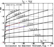
I use this IC - VCE graph
And for Ib = 200uA we have
Ic2 = 6mA for Vce2 = 15V and Ic1 = 5.25mA for Vce1 = 5V
The slope was m = (6 - 5.25) / (15 - 5) = 0.075
y = 0.075x + b
Next we solving for b
6 = 0.075*15 + b ---> b = 6 - 0.075*15 = 4.875
And finally we can find Early Voltage
0 = 0.075*x + 4.875---> x = - b/m = - 4.875/0.075 = - 65V
So Va = 65V
We can do the same for Ib = 150uA
Ic1 = 4mA for Vce = 5V ; Ic2 = 4.85mA for Vce2 = 20V
m = (4.85 - 4)/(20 - 5) = 0.056
b = 4.85 - 0.056*20 = 3.73
And Va = 3.73/0.056 = 66.6V
As you can see we get almost the same result.
Attachments
Bigun,
That's scratching the surface on data for adaptive bias output stages?, but it's the diamond circuit it is the building block for cfa, pp wise. Help me out , have I missed something?, because it seems to only cover open loop diamond output stages mostly but they don't factor in vbe creep. For this the emitter resistor on the output needs to be factored in.
Colin
Chapter 16,which shows that the real efficiency of a Class-A amplifier with a music signal is no better than 1%, which brings into question whether they should ever be built at all.
Do I care how much electricity my amplifier uses, NO. It uses less than the TV and most families have that on most of the time they are at home.
Do I care how much electricity my amplifier uses, NO. It uses less than the TV and most families have that on most of the time they are at home.
But is it Class A?
Yes, we also can use a math in order to calculate the Early Voltage.
As you can see we get almost the same result.
Linear equation, of course. This is more easier.
But is it Class A?
Yep, it's a Pass Aleph 4 running 100W x 2 Class A, inherited from Phil's Dad.
It draws about 400W from the mains supply.
At normal listening it's putting out about 5W so yes it's about 1% efficient.
Member
Joined 2009
Paid Member
Bigun,
That's scratching the surface....
I'm afraid 'scratching the surface' is all I've done with Diamond buffers, although the JLH69 is a design I like and have 80% finished and has half a diamond inside it I guess.
Ultimately the Diamond is made from cascaded emitter followers, the drivers being 'folded' compared with a double EF. The 'tricks' one can do with the current source for the drivers allows you to compensate for current starved outputs or even implement a level of 'error correction' and all sorts of things in-between. Perhaps such trick can be applied to non-folded driver OPS too.
I haven't really looked at this. I only remember Hugh mentioning that he found the information I linked above, to have been useful in his own developments - which you are familiar with but I have not seen nor heard. Therefore, you are the one to be answering the questions
Member
Joined 2009
Paid Member
At normal listening it's putting out about 5W so yes it's about 1% efficient.
that's the thing, the efficiency depends on the rail voltages and normal listening levels.
I figured that a powerful Class AB amplifier might idle away as much heat as a low powered Class A amplifier. With both being used at the same listening levels you have a heck of lot more headroom in the first case, but potentially lower distortion (and an easier time design gin with low or no feedback if you like that sort of thing) in the second case. Pick your poison.
- Status
- This old topic is closed. If you want to reopen this topic, contact a moderator using the "Report Post" button.
- Home
- Amplifiers
- Solid State
- Your opinions are sought on Audio Power Amplifier Design: 6th Edition. Douglas Self