A multi-channel amplifier connected to a multi-channel Source will have loops in the interconnect cable arrangement.
Single or multiple transformers do not remove the input cabling loop.
? where's my hum Andrew , Emotiva UMC-1 source and 5 L15D class D amps , 1 SMPS 2kw Connex PSU , Amp is as quiet as a sleeping forest on a foggy night . Single ended all RCA ( Good quality ) interconnects . NO hum or noise ( apart from the tiny little bit IRS 2092 noise not audible 20 cm away from the speakers )
Cheers ,
Rens
state your output measurements, with and without input cables and with and without input cables connected at the remote ends.? where's my hum Andrew , Emotiva UMC-1 source and 5 L15D class D amps , 1 SMPS 2kw Connex PSU , Amp is as quiet as a sleeping forest on a foggy night . Single ended all RCA ( Good quality ) interconnects . NO hum or noise ( apart from the tiny little bit IRS 2092 noise not audible 20 cm away from the speakers )
Cheers ,
Rens
state your output measurements, with and without input cables and with and without input cables connected at the remote ends.
I must omit my own signature statement here

But , My ears don't lie , I have very efficient Tannoy 15" DC's as speakers .
There is NO hum , whatsoever ! I hate humming amps ( build a lot of them
) and did a lot of research about grounding before I build this amp and I am very happy with the result .I'll agree that measurements will show a difference , but not audible in many cases , and for sure not in my setup !
I'll leave the amps connected for now , so the whole family can keep enjoying them for now , but some upgrades are planned for January and I'll get you the results .
Happy Holidays Andrew !
Cheers ,
Rens
Retired old folk don't get awarded "holidays".
Yes they do
I had 4384 the last 12 years ( Included Leap-Years , I know you are a perfectionist )
Still own my company but haven't worked for 12 years now
Spending all my time in this little nice Lab at home in Brisbane
Sorry about the Thread hijacking ! My last post here ! but will post the measuring results later, and Andrew is probably right , as usual !
You all have a good one in 2015 !
Cheers ,
Rens
Hello
Gee! I completely forgot this Tread that I originally created.
I solved the problem few weeks after my last reply.
Six Cinemag CLMI-15-15 transformers has been ordered and installed with great success.
My noise level on it from preamp and interconnects is so low on each channel that nothing can be heard with ear positionned directly on tweeter, whatever position on pot except...naturally...the 2-3 o'clock where pot's ditributed cap is at worst.
At this specific point one can ear a tiny ultra-low hiss and everything in house has to be shut-off for complete silence.
Noise is so low that it could easily be used as a line amp!!!
I've been listening to it since then and as soon as my dedicated electronic crossover will be ready I'll proceed with few final updates and measurements.
Luke
Last edited:
Hi, Luke
There is little you can do when different sources have different ground reference. Although you have solved the issue by using transformer. I want to mention that by connecting all the AMPs and Devices to a same wall outlet can "localize" ground loop issue. Did you try this?
There is little you can do when different sources have different ground reference. Although you have solved the issue by using transformer. I want to mention that by connecting all the AMPs and Devices to a same wall outlet can "localize" ground loop issue. Did you try this?
I think jdxking is referring to the other necessary system components - the receiver or other audio source units etc. They could well be connected to other mains ring circuits or simply via a large loop area of the installed wiring....connecting all the AMPs and Devices to a same wall outlet...
Introducing a grounded (class 1) DIY amp in an all double-insulated (class 2) HT system has its problems too. That was the reason I didn't bother with DIY for my HT system many years ago but others have done this OK since then. It seems to be popular in Canada as Bigun and MJL21193 come to mind as others here who have who dabbled successfully in DIY multi-channel amplifiers.
However, I'm not making any suggestions here, hopefully just clarifying the issue.
I know its an old thread, but its on top of google search, and this means many may be facing same issues (i did too)
SOLUTION post 17 here.
hum with RCA
I must thank Luke he was patient to try everything and I had (till today morning) same issue. but finally i found the solution for it. this will be helpfull for all new comers making 5.1 or so amps
SOLUTION post 17 here.
hum with RCA
I must thank Luke he was patient to try everything and I had (till today morning) same issue. but finally i found the solution for it. this will be helpfull for all new comers making 5.1 or so amps
Hello arifs
On that time the solution was to use six Cinemag line transormers and paf!...the problem was gone...naturally!
Since four years that Amp is up, perfect and running beautifully..I'd say thanks to myself.
I knew the transformer solution since I ever worked 15 years in sound reinforcement but investing a "surprise" $400 more was a rough idea.
The other solution I should have used despite nobody ever suggested this was to be fully electronically balanced, preamp to amp, but shield (Pin-1) connected to source only...floating earth on shield.
I could not do this as preamp-crossover was finished and had no balanced outputs...only unbalanced...on amp also!
Despite a lot of good constructive points I was already awared of, I've seen a lot of terrible and burlesque suggestions up to the point I almost realized some were "laughing" at me.
Incompetence or arrogance?...who knows.
Yes I've been patient and am definitely not stupid!
After 47 years in Audio one can't know it all but for sure can't be stupid! Please...
So thanks for the good words of yours!
At least I gained this for posting here...after four years.
Arifs, glad to know you found a solution for your project.
Your solution is called a Ground breaker and is the perfect way to couple earth and Audio ground together.
In parallel it's agood thing to add a HV .01µF MKP cap in parallel with resistor.
And also least but not last, say bye bye! to the infamous "ground switch"...you don't need it!
This ground breaker was present the very first time the amp was finished and was not the reason of problem for me as I tested with and without it.
Have a good day!
Luc
Last edited:
stage 1.) You can learn a lot about how to ground an amplifier properly by building an uncased single channel on your work-bench.
stage 2.) You learn more when you insert that single channel in a metal chassis.
stage 3.) There is even more learning by extending those hard learned lessons from the two stages above to a metal cased two channel amplifier.
If you miss out stages one, two and three, it is very difficult to jump straight to stage 9 and hope the learning will be obvious in the mess of cables going literally all over the place.
Go back to stage 1 and learn how to build an uncased mono block, properly !
I forgot about this thread and went back and re-read some of it... his post makes the most sense. I didn't realize how much sense it made when it was posted because I was less experienced.
I just saw R.I.P. under Andrew's name for the first time and I'm really sad. He helped me understand a lot of fundamentals and I'll never forget him. Wish I got to express my appreciation to him before he passed.
For those who go for the isolation solution, here is an inexpensive route:
TY-250P Triad Magnetics | Mouser
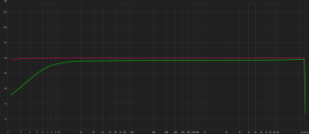
I've included measurements of the frequency response of the transformer compared to a flat loop:
-3dB @6Hz on the low end. About 1dB of signal loss. I have distortion graphs if anyone is interested. Also you can wire it for ~5dB boost in signal with a little steeper low end rolloff.
Attachments
Hi!
I try my question here as well (originally it was posted here).
Question: am I right with this assumption about the RED line current?
What kind of solutions are there (without signal trafo isolation)?
Only a GND loop breaker resistor?
F7 has a current sensing resistor before the P-GND at the PCB.
Isn't this a problem if we apply a breaker resistor between them?
Thanks!
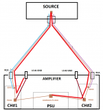
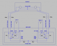
To be honest I'm still confused about this "looped" common RCA + PS
GND layout regarding both hum + common impedance coupling.
I just draw a 2nd image with the same layout showing a possible current path (RED line) via the signal GND loop:
- let's assume there is a large output current impulse on channel #1
- it goes out to the LS and comes back via the LS #1 GND "port"
- then most of it goes of course to the common PS GND via the CH#1 P-GND wire
- but because of the impedance of this wire ("loaded" with the actual output current)
- if there is no current at the moment on channel #2
- a certain current can flow through the signal GND loop the other channels GND
- in this case this current will modulate/distort the original signal
- and in a special way because it's amplitude depends on the difference of the actual output currents of the 2 channels
Any thoughts on that..?
Attachments
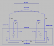
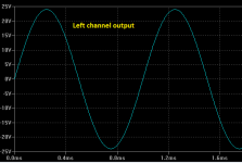
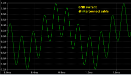
Here are my simulations:
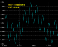
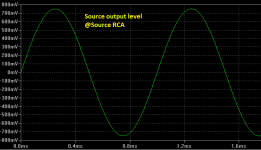
- on the layout you can see the simulated wire impedances: 50m and 100m ohms
- output stages are represented with an ideal voltage source based on the main PS GND
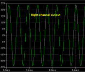
- left channel output is a 1kHz +/-24V sine wave
- right channel output is a 6kHz +/-24V sine wave
- on the last image the current of the interconnect GND wire is shown...
Attachments
Last edited:
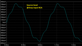
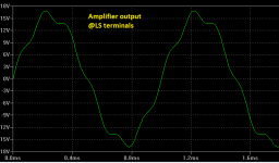
Hi,
I just made a more sophisticated version with:
Here are the results...
Cheers!
I just made a more sophisticated version with:
- signal generators at the source
- input stage simulated with 47k resistor
- output stage simulated with opamp
- applying feedback
Here are the results...
Cheers!
Attachments
It can depend on many variables of exact wiring layout in the amp and source equipment https://www.updatemydynaco.com/documents/GroundingProblemsRev1p4.pdf
- Status
- This old topic is closed. If you want to reopen this topic, contact a moderator using the "Report Post" button.
- Home
- Amplifiers
- Solid State
- Multichannel amplifier internal ground loop