Yes, a snubber of some type is an excellent way to prevent self-oscillation in many hexfets and particularly high transconductance hexfets operating at high rail voltages.
Hugh
Hugh
Hello to all VSQA designers and Builders,
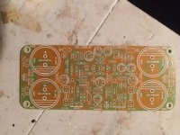
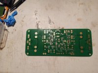
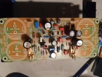
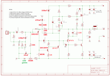
I am building the pcb's designed by Thiago. Listed below are pics of an unpopuated pcb and a semi-populated pcb and also the Schematic I am working from.


A list of the changes made to match the schematic to the pcb:
1. VR1, VR2, and KSC1845 : to match VR1 and VR2 traces to the pcb / schematic I had to mount them backwards from what is shown on the pcb. I mounted them as to what is shown on the schematic. I had to cross the base and collector of the KSC 1845 to match the pcb and schematic. I hope these where correct?
2. I am at the point where I need to follow Hugh's advice and solder one green led in place of the the 2 IN4148 diodes in series or "not". If I do use 1 green led, can I solder it into the pads for one of the IN4148 diodes and use a jumper wire in the next pads for the other 1N4148 diode, or do I have to solder additional extensions on the green led leads to stretch it across the pads for the diodes in series. This all for DC offset adjustment.
If any one has built these, or have any helpful info, I would appreciate your comments.
Thanks,
MM
I am building the pcb's designed by Thiago. Listed below are pics of an unpopuated pcb and a semi-populated pcb and also the Schematic I am working from.


A list of the changes made to match the schematic to the pcb:
1. VR1, VR2, and KSC1845 : to match VR1 and VR2 traces to the pcb / schematic I had to mount them backwards from what is shown on the pcb. I mounted them as to what is shown on the schematic. I had to cross the base and collector of the KSC 1845 to match the pcb and schematic. I hope these where correct?
2. I am at the point where I need to follow Hugh's advice and solder one green led in place of the the 2 IN4148 diodes in series or "not". If I do use 1 green led, can I solder it into the pads for one of the IN4148 diodes and use a jumper wire in the next pads for the other 1N4148 diode, or do I have to solder additional extensions on the green led leads to stretch it across the pads for the diodes in series. This all for DC offset adjustment.
If any one has built these, or have any helpful info, I would appreciate your comments.
Thanks,
MM