HI all,
I started looking at a new amp for a quiet corner of the house to listen to music, since the living room system has been acquired by the kids. While looking at amps, my wife reminded me of the amp that I had carefully stored away some years ago, even though it was bust then. So I dug it out, and the memories came back on it's last moments, they say it's better to burn out than fade away, but I don't think that applies to amps. I remember with terror the brief flash of fire and the rush to the plug before whole system went up in flames.
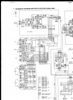
So the main board looks like this
https://plus.google.com/photos/1095...s/5981819875942931889?authkey=CJb4mM2dh5SltAE
The question is do I try to repair it or bin it (obviously in the past I thought I would repair it, because I loved it sound)
I know the most things can be repaired, it's a matter of time, money and expertise. latter it is my week point, I have fixed lot of gadgets and know my around a multimeter & soldering iron, but also fail my electronic O-level.
Obvious thing would be to replace the burnt out component, but I guessing the burn out not the root cause but a result of an underlying problem. I have no idea of how to do the fault analysis to identify the issue.
From searching on the web this forum seems to have the best knowledge, so drawing on that and looking at the board is it worth repairing at all?
Thanks
Phil
I started looking at a new amp for a quiet corner of the house to listen to music, since the living room system has been acquired by the kids. While looking at amps, my wife reminded me
of the amp that I had carefully stored away some years ago, even though it was bust then. So I dug it out, and the memories came back on it's last moments, they say it's better to burn out than fade away, but I don't think that applies to amps. I remember with terror the brief flash of fire and the rush to the plug before whole system went up in flames.So the main board looks like this
https://plus.google.com/photos/1095...s/5981819875942931889?authkey=CJb4mM2dh5SltAE
The question is do I try to repair it or bin it (obviously in the past I thought I would repair it, because I loved it sound)
I know the most things can be repaired, it's a matter of time, money and expertise. latter it is my week point, I have fixed lot of gadgets and know my around a multimeter & soldering iron, but also fail my electronic O-level
. Obvious thing would be to replace the burnt out component, but I guessing the burn out not the root cause but a result of an underlying problem. I have no idea of how to do the fault analysis to identify the issue.
From searching on the web this forum seems to have the best knowledge, so drawing on that and looking at the board is it worth repairing at all?
Thanks
Phil
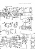
That should be an easy fix but to repair it via a forum means you need to have a copy of the circuit to refer to.
There will be little more than failed output transistors, drivers and a few associated small parts that got taken out along the way... but a diagram is essential. Now I looked at a couple of the usual suspects for a manual and this model wasn't listed... so that's the first problem
There will be little more than failed output transistors, drivers and a few associated small parts that got taken out along the way... but a diagram is essential. Now I looked at a couple of the usual suspects for a manual and this model wasn't listed... so that's the first problem
By all account the PM66SE KI came with manual, certificate, and circuit diagram, although I don't think mine did.
I did some googling and found this.
Sunshine Electronic Norge MARANTZ PM-66KI Service Manual free download,schematics,datasheets,eeprom bins,pcb,repair info for test equipment and electronics
Which on my limited inspection looked good, well to me at least
I did some googling and found this.
Sunshine Electronic Norge MARANTZ PM-66KI Service Manual free download,schematics,datasheets,eeprom bins,pcb,repair info for test equipment and electronics
Which on my limited inspection looked good, well to me at least
Excellent...
OK, the only possible problem I see is the scenario of the AN7062 IC being faulty and getting a replacement. It is listed as available from CHS (Charles Hyde), hopefully though he IC is OK.
Search results for AN7062
If you want to attempt this then the procedure is to do some basic checks to get an idea how far back (or more correctly forward) the damage extends.
Replacing T6, T7, T8 and T9 will ultimately be needed.
R24/25 the 0.1 ohms highly likely to have failed... so measure them. They would be replaced with separate 0.1 ohms rather than one with a common centre connection.
Check R22 and R23.
Check R21
Check R20
Check R17 and R18
Check R11, R16 and R19
Those are all low value resistors and should be checkable in circuit. I would recommend removing T6, T7, T8 and T9 first because these are going to be zapped and being short circuit will affect readings.
If you decide you want to have a go at this then we would probably use different semiconductors that are easily available.
Unfortunately, until it is all rebuilt, there is no way to easily test the IC. If the present damage is confined just to the output stage and drivers then there is a good chance the IC is OK. That is what checking all those parts above will hopefully prove.
Thanks, I think I will attempt a repair.
If the AN7062 IC is really available then I may just go head and replace it, it's not a great deal of money.
I assume the T6 - 9 are the larger power transistors? (labeled on the board as Q762, Q764...) What about the smaller versions (Q752), should they be removed as well?
A bit more of showing my ignorance, i'm assuming R22 = R722 marked on the circuit diagram and board?
I couldn't see any resistor mark at 0.1 ohms, R24 = 100k Ohms and R25 = 68k Ohms. R23/R25 seemed to be paired and on the other channel R24/R26.
and I totally didn't get "They would be replaced with separate 0.1 ohms rather than one with a common centre connection." statement with relation to R24/R25
thanks
Phil
Wow, Mooly, CHS are expensive.
Cricklewood Electronics - CCTV. CCTV Equipment. CCTV Systems. Digital CCTV Cameras
£3.50 from here.
Cricklewood Electronics - CCTV. CCTV Equipment. CCTV Systems. Digital CCTV Cameras
£3.50 from here.
Hi
At lunch I took some reading on resistors (but without any components removed). The results looked encouraging
# markup actual Comment
R711 10k 9.94k
R712
R713
R714
R715 Link
R716 Link
R717 Link
R718 Link
R719 68 69.7
R720 68 71.4
R721 68 70.4
R722 68 70.3
R723 100k 99.9k *not stable
R724 100k 99.7k *not stable
R725 68k 67.8k
R726 68k 67.8k
Thanks, I think I will attempt a repair.
If the AN7062 IC is really available then I may just go head and replace it, it's not a great deal of money.
I assume the T6 - 9 are the larger power transistors? (labeled on the board as Q762, Q764...) What about the smaller versions (Q752), should they be removed as well?
A bit more of showing my ignorance, i'm assuming R22 = R722 marked on the circuit diagram and board?
I couldn't see any resistor mark at 0.1 ohms, R24 = 100k Ohms and R25 = 68k Ohms. R23/R25 seemed to be paired and on the other channel R24/R26.
and I totally didn't get "They would be replaced with separate 0.1 ohms rather than one with a common centre connection." statement with relation to R24/R25
thanks
Phil
The 0.1 ohms are the 3 legged white oblong components. They should read 0.1 ohms from the centre lead to each end, and 0.2 ohms from end to end of course.
The component references will probably have a prefix (such as the 7) to distinguish left and right channels. So R22 on one channel may be R722 on the other and so on.
Lets be certain that the circuit diagram really does tally with the actual board in front of you... and I have doubts... it looks different. For example in your picture the two output transistors at the bottom are marked Q762 and Q764. The output transistors on the diagram are T8 and T9. So something is very different.
I wonder if there was a mk1 and mk2 version ? Whatever, its a major stumbling block because it makes it much much harder for you to identify the major components. Its still not impossible to do but it is much more difficult.
I wouldn't replace the IC in hope... there is a good chance it is OK.
Wow, Mooly, CHS are expensive.
Cricklewood Electronics - CCTV. CCTV Equipment. CCTV Systems. Digital CCTV Cameras
£3.50 from here.
Mmmm
Hi
At lunch I took some reading on resistors (but without any components removed). The results looked encouraging
# markup actual Comment
R711 10k 9.94k
R712
R713
R714
R715 Link
R716 Link
R717 Link
R718 Link
R719 68 69.7
R720 68 71.4
R721 68 70.4
R722 68 70.3
R723 100k 99.9k *not stable
R724 100k 99.7k *not stable
R725 68k 67.8k
R726 68k 67.8k
That's good
Only low value resistors will have failed in all this. That's anything below say 1 or 2k and in practice probably only anything below 200 ohm or so. And those that you marked as not stable... that's normal and is just interaction of the meter test voltage with other components in circuit. Biggest problem up to now is getting a correct diagram.
Last edited:
HI
I checked the link that I pasted up and it was the wrong one. This version will make a lot more sense.
Marantz PM-66SE Service Manual free download,schematics,datasheets,eeprom bins,pcb,repair info for test equipment and electronics
So far all the values have been corrects, and so far I've not found anything on the diagram that's not on the board and vica verse
sorry about that
No problem although I see its a .rar file. Can you post a .jpg of it ?
It will be tomorrow before I can take another look, but with the correct circuit all things are possible. Have a check of the low value resistors around the zapped transistors and we'll take it from there.
although I see its a .rar file. Can you post a .jpg of it ?It will be tomorrow before I can take another look, but with the correct circuit all things are possible. Have a check of the low value resistors around the zapped transistors and we'll take it from there.
Thanks, got the full 8mb one too.
OK... so the resistors to check are,
R767 that's the dual 0.1 ohm.
R765 and R773. Both 2.2 ohm.
R763 a 330 ohm.
R757 and R759. Both 100 ohm
R761 a 1k
The transistors Q761 and Q763 are zapped. The driver transistors would be replaced anyway whether they read OK or not. That's Q757 and Q759. The pre drivers, Q753 and Q755 would also possibly be replaced.
Lets see what the damage is first.
To test the amplifier it will all have to be built up correctly. It looks like you can access the underside of the PCB when its all assembled ?
For powering up the amplifier initially we use a "bulb tester" which is a 60 or 100 watt mains filament bulb in series with the mains. This limits current and prevents damage if there is a problem.
Can you remember if the other channel was OK at the time it was all last used ?
ok
R757 = 98.2
R759 = 99
R761 = 1006
R763 = 323.5 - this is the final value as it climbs as if influenced by a capacitor (also casing slightly brown) - it's sister R764 is 330 rock solid no climb
R765 = 2.7 *
R767 = not infinite, but I think one of my multimeter leads is duff as put together they read .9. I couldn't get a reading that I was happy with. both R767 & R768 seem to give the same result
R773 = 2.7 casing looking chipped a one terminal end *the colour code on the casing are hard to make out, they really dont look like red.
I think the other channel was ok, but I do remember having problems with one of the channels and getting R802/R804 replaced as there is a common fault where this go. but which one it was, it was significant time ago , my gut is telling me that is was the channel that went was the channel with the fault.
Last edited:
That all sounds promising. The fact that R757/759 look OK suggest that hopefully the IC will be OK.
R802/804 are in the power supply and failure of these would remove the supply to the preamp stages... so common to both channels. Its worth measuring them now though.
The 0.1 ohms are critical components. A good way to measure them is to solder wire to them and trap that wire in your meter sockets. Assuming your meter acurrately reads so low then you will get a good idea... but its no biggy just to replace them and be done with it.
So, up to now we are looking at a typical failed output stage that needs replacement transistors and possibly a few resistors too.
When the unit is assembled do the original transistors use insulating kits which would consist of a mica or neoprene pad and perhaps an insulating bush in the screw hole to stop the metal back of the transistor contacting the chassis. Or were the transistors all plastic backed ?
Finally a couple more resistors to check R733 and R734 both 10 ohm.
- Status
- This old topic is closed. If you want to reopen this topic, contact a moderator using the "Report Post" button.
- Home
- Amplifiers
- Solid State
- Marantz PM-66SE KI - bin or repair?