Thank you, OS.
It is DIY. If someone decide to follow your design (I will), he/she can use various parts. It may have different height than your components choice.

Even as I considered the OPS cap heights in making the IPS's , some may want
the IPS component's "facing away".
A "flipped around" (reverse polarity) OPS now exists.
IPS's will just be attached .."reverse" ( + / -)
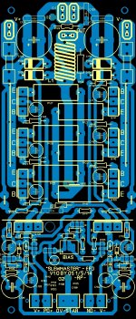
" Slewmaster RP" ... below - have to relabel components..
PS - now I know .... 2- 3-pair version (slew3-main /RP) and 2 5-pair version (slew5-main/RP)
4 OPS's for whatever application. IPS's will remain the same - can be used in any OPS.
OS
Attachments
Last edited:
Nice looking layout and board. When will the first one be up and running? Looking forward to the listening results.
NAF and AJT are both etching. NAF showed his a few posts back.
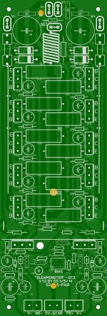
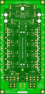
As promised , a reverse polarity 3-pair board is below along with the
"normal 3-pair"
Moved the cap multiplier components back and the IPS/OPS interface
right to the edge. (more room).
I misquoted the cap multiplier. A 5mm LS- 330uF/100v is the largest one that will fit.
It is 12.5mm X 25 mm ... with the added room ,no issue !
NAF .... your board is good , you can use a 100uF- 220uF 100v cap with a
higher HFE device for the multiplier semi. you CAN use the 330u if you keep
your VAS heatsink at 12-15mm height . Both VAS's on the IPS boards are
exactly 4.5mA - they should run VERY cool
 .
. BIAS trimmer and the wolverine CCS adj. will be unobstructed with ANY
of the boards.
Also , a 5 -PAIR "slewMONSTER" OPS is below - for power hogs !
3 excellent OPS 's , the 2- 150-250W - 8/4R "3P's" and the 250/400W "5P"
PS - "5P" with better devices could be 400/700W (8/4 R) !! Like the HK990 !!
5P also has more room for larger driver heatsink - even an "anal" one ..
Edit -- really, really.. tweaked the layout on these 3 ... art !!
OS
Attachments
Last edited:
20'th century layout ....
I will and I won't offer apology ...
You CAN use those 20'th century ceramic resistors (26mm LS) ... or
http://www.koaspeer.com/catimages/Products/MOS/MOS.pdf
$1 apiece , metal oxide non-inductive 24mm LS.
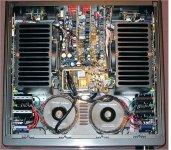
I mentioned a Harmon kardon 990 OPS (below) , I have seen one in real life .
Ha ha , they solder the Re's right to the back of the board - IPS is a
tiny SMD one ... it is the "leach front end" with my slewmonster OPS.
It IS FR-4 , at least . Layout (even the traces)... is the same , with 5 pair MJLxxxx. 1 pair
is thermaltrak (diode inside the OP transistor). It controls a similar Vbe
as the slewmaster. PS caps are onboard ...(to save $$).
Specs are below .. Harman Kardon HK 990 integrated amplifier Page 2 | Stereophile.com
the OPS itself should be the same (or even inferior)
to the slewmaster .... we use better power supplies.
ALL for under 2500$$ .. O boy ... would it not be wild if the 50$ DIY "slewmaster"
-wipes the floor-- with it !!
I will and I won't offer apology
...You CAN use those 20'th century ceramic resistors (26mm LS) ... or
http://www.koaspeer.com/catimages/Products/MOS/MOS.pdf
$1 apiece , metal oxide non-inductive 24mm LS.
I mentioned a Harmon kardon 990 OPS (below) , I have seen one in real life .
Ha ha , they solder the Re's right to the back of the board - IPS is a
tiny SMD one ... it is the "leach front end" with my slewmonster OPS.
It IS FR-4 , at least
. Layout (even the traces)... is the same , with 5 pair MJLxxxx. 1 pairis thermaltrak (diode inside the OP transistor). It controls a similar Vbe
as the slewmaster. PS caps are onboard ...(to save $$).
Specs are below .. Harman Kardon HK 990 integrated amplifier Page 2 | Stereophile.com
the OPS itself should be the same (or even inferior)
to the slewmaster .... we use better power supplies.
ALL for under 2500$$ .. O boy ... would it not be wild if the 50$ DIY "slewmaster"
-wipes the floor-- with it !!
Attachments
Amp of the week --(next one).
I think the "Symasui" is worthy of being put to board.
It's LTP X 2 with lead/lag compensation , while being a little harder
to "tweak" ( as compared to MIC or TMC) .. once it is done - a REAL
stable amp.
Member andewlebon built the sansui like this , and it worked first time
on a perf board. Not a touchy amp with the proper capacitors (compensations).
It behaves a little like a CFA in it's bode , a flat OLG that does not drop
until it is a couple decades past 20K. But ... it is still a VFA.
I added the more balanced SYMASYM VAS to it , and it "screams".
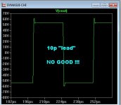
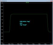
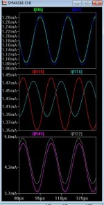
over 100V/us slew. (below 1/2 - 110V in .7uS) - not good with 10p "lead" ...
15p is needed to stop "ringing" (below 2)
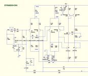
The circuit is (below 3) .... R8 , C5 and C6 are the "players" to make a stable amp .
Sansui uses 33R, .0022u ,and 22p for these components. I'm not
far off with the simulator.
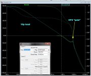
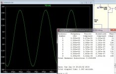
Now to the bodes ... (boring but essential) . (below 4 is a 10mhz "spike" - OPS Q ) ... this is why it "rings".
Phase margin is good , that's why it does not just oscillate !
If you make C6 too big (22p) , the "spike" re -appears (and overshoot)
You can use this much "lead" with a bigger C5 and/or lower R8.
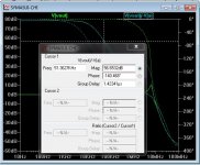
(Below 5) is with 10R /.0022u/15p (R8/C5/C6) - notice the high gain
of 80db right to 40k (56db at 50K!!) where it begins to slope like a normal VFA (blameless).
More like a CFA ... it should have stellar THD at 50k (THD50) ...( last attachment) !!
Nice 21ppm at 3R .. like a CFA - even.
Touchy , touchy .... but this one is 33 years old !!!
OS
I think the "Symasui" is worthy of being put to board.
It's LTP X 2 with lead/lag compensation , while being a little harder
to "tweak" ( as compared to MIC or TMC) .. once it is done - a REAL
stable amp.
Member andewlebon built the sansui like this , and it worked first time
on a perf board. Not a touchy amp with the proper capacitors (compensations).
It behaves a little like a CFA in it's bode , a flat OLG that does not drop
until it is a couple decades past 20K. But ... it is still a VFA.
I added the more balanced SYMASYM VAS to it , and it "screams".
over 100V/us slew. (below 1/2 - 110V in .7uS) - not good with 10p "lead" ...
15p is needed to stop "ringing" (below 2)
The circuit is (below 3) .... R8 , C5 and C6 are the "players" to make a stable amp .
Sansui uses 33R, .0022u ,and 22p for these components. I'm not
far off with the simulator.
Now to the bodes ...
(boring but essential) . (below 4 is a 10mhz "spike" - OPS Q ) ... this is why it "rings".Phase margin is good , that's why it does not just oscillate !
If you make C6 too big (22p) , the "spike" re -appears (and overshoot)
You can use this much "lead" with a bigger C5 and/or lower R8.
(Below 5) is with 10R /.0022u/15p (R8/C5/C6) - notice the high gain
of 80db right to 40k (56db at 50K!!) where it begins to slope like a normal VFA (blameless).
More like a CFA ... it should have stellar THD at 50k (THD50) ...( last attachment) !!
Nice 21ppm at 3R .. like a CFA - even.
Touchy , touchy .... but this one is 33 years old !!!
OS
Attachments
Sch from #225 reminds me on a copying analog tape recordings three to four times. Fourth copy isn't anywhere near original, preservation of original signal integrity is very low.
Yes , this one does all the "bad things" CFA eliminates. (phase wise)
"signal integrity low" ? Actually - this amp is one of the better "sounding"
VFA's , most still work 30 years later w/recap's.
Date codes on the sanken output's are '79 .
Phase is "all over" -below(ltp- 1/ ltp-2 /vas) ...
OS
Attachments
Is that MT-200 style sanken outputs?Yes , this one does all the "bad things" CFA eliminates. (phase wise)
"signal integrity low" ? Actually - this amp is one of the better "sounding"
VFA's , most still work 30 years later w/recap's.
Date codes on the sanken output's are '79 .
Phase is "all over" -below(ltp- 1/ ltp-2 /vas) ...
OS
I have a question why not mount all the OPS transistors on same heatsink?
With separate heatsink we need to know how large it should be
(maybe the builder will make it larger or smaller than it should be)
Sorry for asking this but I like one heatsink for all if possible
Is that MT-200 style sanken outputs?
I have a question why not mount all the OPS transistors on same heatsink?
With separate heatsink we need to know how large it should be
(maybe the builder will make it larger or smaller than it should be)
Sorry for asking this but I like one heatsink for all if possible
2 heatsinks - 2vbe's = 1mv bias stability (hk680)
Driver heatsink can be just 50 X75mm piece of AL or CU .
can't get more simple than that !
OS
Not = Better design flow, reduces trace lengths and the effects.I have a question why not mount all the OPS transistors on same heatsink?
Alway's thought the long traces to the vbe multiplier sense device was an Achilles heal. Find a method to couple the heat to the vbe multiplier sense device, instead of long traces to the device mounted on the main HS.
I see, that's why we must use 2 vbe's & 2 heatsinks2 heatsinks - 2vbe's = 1mv bias stability (hk680)
Driver heatsink can be just 50 X75mm piece of AL or CU .
can't get more simple than that !
OS
Thanks uncle OS
Hi Rsavas, thanks for more explanationNot = Better design flow, reduces trace lengths and the effects.
Alway's thought the long traces to the vbe multiplier sense device was an Achilles heal. Find a method to couple the heat to the vbe multiplier sense device, instead of long traces to the device mounted on the main HS.
Regards
John
I see, that's why we must use 2 vbe's & 2 heatsinks
Thanks uncle OS
Hi Rsavas, thanks for more explanation
Regards
John
As Rsavas says - long traces on vbe will be capacitive. On an EF3 , things
are more sensitive still. Just a couple microamps = AMPS.
Notice my Vbe(s) are- right on- the devices being compensated for. Q104
on the 'slewmaster EF3" is 20mm away from one of the output devices without being near any of the current traces from those output
transistors - IDEAL ! The HK680 is configured the same way ....
OS
I was buy some Caddock MP915 TO-126 0R25/15W/1%.
Mouser sell 3.77$ per one.
They're great for emitter resistors.
They are $5.01 here ... wow!
PS - they were the ones that i mentioned for the CFA amp , to eliminate thermal distortion in the feedback
divider. Cheaper metal film 3-5W devices for OP Re are a better bet.
OS
Last edited:
I designed my VFA amp (X250) with OPS module look like, not bad. No oscillation. PCB track long a bit, but symmetry between pos. & neg. rail signal.
I tried to put all transistors of OPS on a heatsink, to thermal coupling.
Emitter resistors are 4 x Vishay BC PR02 Metal film 1R/2W/5%/250ppm paralled. They're cheap in Mouser, 6.2$ for 100pcs.
I tried to put all transistors of OPS on a heatsink, to thermal coupling.
Emitter resistors are 4 x Vishay BC PR02 Metal film 1R/2W/5%/250ppm paralled. They're cheap in Mouser, 6.2$ for 100pcs.
Attachments
I designed my VFA amp (X250) with OPS module look like, not bad. No oscillation. PCB track long a bit, but symmetry between pos. & neg. rail signal.
I tried to put all transistors of OPS on a heatsink, to thermal coupling.
Emitter resistors are 4 x Vishay BC PR02 Metal film 1R/2W/5%/250ppm paralled. They're cheap in Mouser, 6.2$ for 100pcs.
Looks like you use a standard single Vbe for the EF3 , you do not need to heatsink the predrivers (2-3ma). Sansui Z3900 is the same.
A Vbe like this ignores the predrivers and compensates the (fixed)temperature
co-efficient of the (main)driver + outputs just like a EF2.
PS - what makes the 2 Vbe work so well is the ability to change the co-efficient (not fixed).
This would be like dynamically changing the collector to base resistor value on your Vbe - in response
to both ambient and main driver temperature.
OS
Last edited:
Which amp ?
CFA/hawksford Cascode can use a green,white or UV led (cool). be sure of at least
2.5V forward voltage drop.
I specified UV , as it has a perfect 3-3.1V Vf . White is 3.6V + and green is
2.3 -2.6V.
CCS LED's are standard 1.6V - 1.8V Vf red leds. Older low brightness red's
often have this low forward voltage.
Cap multiplier semi's can be 120V Vce or above. Hfe from 80 -250.
Higher hfe = Cap value X hfe = bigger "false" capacitance.
OS
- Home
- Amplifiers
- Solid State
- Slewmaster - CFA vs. VFA "Rumble"