Member
Joined 2009
Paid Member
i am sure your project your project is likewise good, just that smd scares me at the moment...😀
You are not alone in being nervous about SMD construction, it is best for people who are short sighted 🙂
Ostripper, If you have time please look IPS of The Ampz Pages - the DPA 220. It have nice clipping behavior. Can you optimize the IPS?
I simulating your DIYA amp, but I have nasty clipping behavior at one side of power supply.
Yes , Diya's amp now has a added saturation diode in version 2.4 ...
This is inherent in ALL the "blameless" projects here at diya. Tried to explain
this to other members .. got yelled at !! 😀
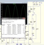
This one is "fixed" (REALLY fixed) .... clip it /stomp it , even the big CCS
has minimal saturation/fast recovery.
(below) , I did 1R !! with the EF3.... still sub PPM 1K (12ppm 20K).
Also , the .asc is below - set for 1K-1/2 power - 1R !
OS
Attachments
Ostripper, If you have time please look IPS of The Ampz Pages - the DPA 220. It have nice clipping behavior. Can you optimize the IPS?
I simulating your DIYA amp, but I have nasty clipping behavior at one side of power supply.
That is very interesting , a "leach" like front end with a folded cascode VAS.
We could "tweak this" !! 😀
PS - this amp would like a servo ... why i don't usually design VFA symmetrical.
OS
You are not alone in being nervous about SMD construction, it is best for people who are short sighted 🙂
Near Sighted as in NEAR Sighted😱 😱 😱
Hehehe, there's plenty of short sighted folks here too, thankfully flinging poo at one another elsewhere...
As for SMD, I have yet to design with it but I will likely be headed in that direction sooner rather than later. Repairs were never that bad with SMD, so new construction should be easy enough especially with some of the medium to larger package sizes.
As for SMD, I have yet to design with it but I will likely be headed in that direction sooner rather than later. Repairs were never that bad with SMD, so new construction should be easy enough especially with some of the medium to larger package sizes.
For SMT, you need a bit more equipment, as a min,
tweezers and 2 irons? why, it is so easy to remove a SMT passive with 2 irons.
Need small gauge solder 0.015"(no-clean glow core), few sizes of solder wick. Jewelers loupe 10x, head band is even better.
Pick 0805/1206/1210+ as a easy to use passive package.
OS thx for the design, can't believe the results. Nice to see you found those ON/Sanyo bjt's as well and making good use of them.
I have taken your bjt libs added to what I have and sorted, so easy to manage. Will post for you and other to replace "standard.bjt"
Attachments
SMD might be good for pre-matched applications.
This one .. http://www.onsemi.com/pub_link/Collateral/BC846BPDW1T1-D.PDF
-would be the one for my 12V regulated CFA diamond.
For the wolverine , an added cascode would be required to
use these ....
http://www.nxp.com/documents/data_sheet/BCM847BV_BS_DS.pdf
NO matching , NO thermal coupling.
But , to-92 is just fine ... most badger builders report just a few mV offset
without trimming - just a crude DMM match will do.
The "wolverine" is a comin' along - just the input filter now. (finished tonight)
OS
Attachments
If you want to easily perform SMT assy and rework manually , the easiest way is to use a knife shaped soldering iron tip such as this one:
XNT KN - WELLER - TIP, KNIFE, 2.0MM | element14 Australia.
This way you can use the side of the tip to desolder both ends of SMT resistors, caps at the same time - saving your PCB pads.
This tip along with a pair of curved tweezers and a magnifying lens with light is the way to go.
XNT KN - WELLER - TIP, KNIFE, 2.0MM | element14 Australia.
This way you can use the side of the tip to desolder both ends of SMT resistors, caps at the same time - saving your PCB pads.
This tip along with a pair of curved tweezers and a magnifying lens with light is the way to go.
Hehehe, there's plenty of short sighted folks here too, thankfully flinging poo at one another elsewhere...
As for SMD, I have yet to design with it but I will likely be headed in that direction sooner rather than later. Repairs were never that bad with SMD, so new construction should be easy enough especially with some of the medium to larger package sizes.
That's funny .... "slingin' poo !! 🙂
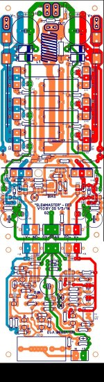
Looking at the SMD BCxxxx packages , a perfected wolverine would benefit
from smaller traces and shorter runs in the LTP/CM/VAS area.
Finding higher voltage SMD is hard ... 180V is only 5550/5551 in smd
I think the best is a mix... to-126 for the VAS, and smd for everything else.
OS
thanks OS, now off to pcb making....
Absolutely double check this material.
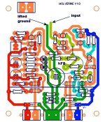
attached is the wolverine + OPS.
I still can't find an error , but I'm shortsighted .😀
IPS component's face OPS component's with boards at 90 degree angle.
With a symmetrical amp layout , both IPS's will be at the back of the amp.
At th e90 degree angle - OPS NFB will go either through or over the
driver HS aimed right at the pad on the IPS. (insulate or shield it).
G2 can go under or around the OPS board.
OS
Attachments
Interconnect ...
Wire wrap pins are screwed tightly into the euro terminals.
Then you line up the IPS and solder.
When all is done , simply unscrew the euro-terminals to remove IPS.
You also could use a wirewrap terminals for NFB ,as to facilitate unsoldering
the NFB return wire.
Having the NFB return soldered is a good idea , you would not want
the amp going open loop.
OS
Absolutely double check this material.
attached is the wolverine + OPS.
I still can't find an error , but I'm shortsighted .😀
IPS component's face OPS component's with boards at 90 degree angle.
With a symmetrical amp layout , both IPS's will be at the back of the amp.
At th e90 degree angle - OPS NFB will go either through or over the
driver HS aimed right at the pad on the IPS. (insulate or shield it).
G2 can go under or around the OPS board.
OS
Ostripper, may be better to face of the IPS's PCB pattern to the OPS PCB, so we are not limited by the height of components.
Ostripper, may be better to face of the IPS's PCB pattern to the OPS PCB, so we are not limited by the height of components.
But your not , the OPS multiplier caps are 25mm max height ,
the first "tall thing" on the IPS is the VAS heatsink (27mm off the bottom).
Worst case , the VAS heatsink can be a 12-15mm piece of aluminum
(not high).
I have considered physical size limits.
PS - I will consider this.... EDIT - swapping the polarity of the OPS board (the Vbe) will allow the pattern
to face the OPS. This would only require rework of the Vbe and reversing all capacitors/diodes.
(most of the PCB is symmetrical).
Any feedback on this is welcome , I could make the change in an hour (or 2).
OS
Last edited:
Thank you, OS.
It is DIY. If someone decide to follow your design (I will), he/she can use various parts. It may have different height than your components choice.
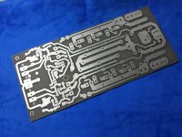
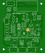
That came out SO perfect. Good TT !!My first step, making Slewmaster v.1.1 OPS board...
OS
That came out SO perfect. Good TT !!
OS
Thank you, next is input stage board... and i could try as many of your very good design 🙂
My first step, making Slewmaster v.1.1 OPS board...
Wow... very fast....
I just finished draw my OPS. I add RC on basis of the driver like Dadod did in his TT amp and I want to draw 2 Lateral Mosfet for other OPS.
- Home
- Amplifiers
- Solid State
- Slewmaster - CFA vs. VFA "Rumble"