Dadod, you are absolutely correct in the differences between CFA vs VFA. Both work OK, mostly, but the 'downside' of CFA is bias stability and the 'downside' of VFA is added complexity of the through-path.
I first started with CFA (complementary single devices) back in 1967, but quickly switched to VFA (complementary differential) input stages in 1968, and seldom looked back, because of a number of advantages, bias stability being dominant.
As far as slew rate is concerned, I am of the opinion that 'all else being equal' a higher slew rate is preferred, but anything beyond 100V/us is usually not encountered in the real world, as shown by years of looking for it in the most exotic source material.
In my opinion there is nothing wrong with CFA, IF you do it right, and today that is easier than it was in 1967. However, there is nothing wrong with VFA either, and the slew rate that I finally reached about 30 years ago was about 500V/us on a single side (not bridged) power amp. But IF I needed 1000V/us on a single side, I would probably go for CFA from the start, and it may be that CFA has some intrinsic property that makes it very worthwhile to attempt, I cannot know this for sure.
Last edited:
Dadod, you are absolutely correct in the differences between CFA vs VFA. Both work OK, mostly, but the 'downside' of CFA is bias stability and the 'downside' of VFA is added complexity of the through-path.
I first started with CFA (complementary single devices) back in 1967, but quickly switched to VFA (complementary differential) input stages in 1968, and seldom looked back, because of a number of advantages, bias stability being dominant.
As far as slew rate is concerned, I am of the opinion that 'all else being equal' a higher slew rate is preferred, but anything beyond 100V/us is usually not encountered in the real world, as shown by years of looking for it in the most exotic source material.
In my opinion there is nothing wrong with CFA, IF you do it right, and today that is easier than it was in 1967. However, there is nothing wrong with VFA either, and the slew rate that I finally reached about 30 years ago was about 500V/us on a single side (not bridged) power amp. But IF I needed 1000V/us on a single side, I would probably go for CFA from the start, and it may be that CFA has some intrinsic property that makes it very worthwhile to attempt, I cannot know this for sure.
Thank you John for your explanation. I will build the CFA for sure, I am intrigued with so many people saying it sounds better then the VFA, but so many projects on wait list. The easiest way to go the CFA path is to convert one of mine JLH mosfet amps to CFA(I think that with lateral OPS is going to be easier). Have you seen this amp, http://www.diyaudio.com/forums/solid-state/243481-200w-mosfet-cfa-amp-46.html#post3771044 , I would like your comments.
BR Damir
90V/us measurement was for the 50W/8 ohm amplifier. I still think it is not needed and that 20V/us would probably do the job as well. Also, I do not think that CFA x VFA discussion makes any sense. It is about implementation and REAL design, not about fight on topologies.
It is also possible to combine both principles together. You just have to put a buffer before the inverting input. Disadvantages are solely the large number of components.
For example
For example
It is also possible to combine both principles together. You just have to put a buffer before the inverting input. Disadvantages are solely the large number of components.
For example
")
And, if you do that with a simplified CFA circuit you get a JCurl IPS with advantages of both.
Thx-RNMarsh
Of course you are right. Meant with "my rule of thumb factor" that this is only valid for my blameless project.
The question: is it valid to compare two (partially different) circuits with different bjt models and to conclude the real life measurements from one project can be transferred as prediction for the other project?
At least in the case of a "blameless" , the topology is 95% of the result.
Many models will give the 5-10ppm THD 20.
Unless , in the advent of a MAJOR layout error .. such as long ground loops
or a poor NFB takeoff -" real life" should be pretty close.
I saw your layout AND the long "dongle" between IPS/OPS ! Still you get
PPM THD. So , the topology "forces" good performance.
Very good design , BTW. I studied it.
OS
Looks pretty good, but where are the low value power supply bypass caps?
That is an other controversial theme, some says that it could do more harm then good, I don't have enough practical experience to say what is better. In some of my VFA amp I used small SMD ceramic caps(0.1 uF) soldered directly on the back of the big electrolytic caps, and did not notice any ill effect or degradation of the sound. But then is some of my amps I did not used them and it sounded good. John what cap value you suggest, and what cap type?
And, if you do that with a simplified CFA circuit you get a JCurl IPS with advantages of both.
Thx-RNMarsh
follower driving the input for low distortion and add a folded cascode and your there --
View attachment Derived.pdf
Thx-RNMarsh
We use 0.1uF polystyrene.
I never go below .1mfd. Higher is OK as well.
THx-RNMarsh
We use 0.1uF polystyrene.
It must be quite a chunk. I think that 0.1 u ceramic C0G(I used X5R) could be good to, but it's not easy to find it.
While we are on the subject of decoupling, have read that you need to take into account the DC bias with ceramic caps. This can apparently result in quite a large reduction in the capacitance. Have I understood this correctly? Also, does this apply to film caps as well? Have tried to research the answer but failed so far.
While we are on the subject of decoupling, have read that you need to take into account the DC bias with ceramic caps.
Yes .... and it depends on many things.
Attachments
While we are on the subject of decoupling, have read that you need to take into account the DC bias with ceramic caps. This can apparently result in quite a large reduction in the capacitance. Have I understood this correctly? Also, does this apply to film caps as well? Have tried to research the answer but failed so far.
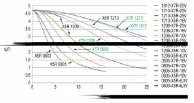
Yes for class II capacitors, no for class I capacitors (such as NP0, a.k.a. C0G). At work we once had a 10 uF, 6.3 V X5R capacitor that turned out to have a capacitance of only 4 uF, because there was 3.3 V across it.
Class I capacitors are actually pretty good capacitors, but they are only available in small values.
Class II capacitors are available in large values, but they are temperature dependent, nonlinear, have a relatively low Q and quite some dielectric absorption. X7R is bad, X5R is even worse, Y5V and Z5U are again worse. Mind you, when you only use them for supply decoupling, low Q is an advantage and I can't think of any reason why dielectric absorption would be a disadvantage.
Last edited:
- Home
- Amplifiers
- Solid State
- CFA Topology Audio Amplifiers