Is this what you are using ?
I see you use Jfet CCS's , and run the Cascode "HOT" .
I forgot the french designer ... but he also used the "magic" 4.7R between
active and cascode....
aaaah .. google found it - Memory Distortion Philosophies - Part 5 : Circuits, continued
"brainwashing the VAS"funny !
He never envisioned this for a CFA.
Does it "sing" ??
OS
I use the jfet because I have it. I just try my first CFA design. Don't laugh at me. I still learn.
I can made it singing. But I still do not satisfied yet. It is dead silent without input signal, has good square wave response. But when compare the sound to my VSSA variant, my VSSA variant is more easy listening.
Next time I will compare it more carefully.
Perhaps simple is better. My VSSA variant equals the THD of the
2 stage with half the devices. THD is not everything ....
less group delay = easy listening ??
PS -The "hot hawksford" has much more distortion than one at 4-5ma.
OS
This is what I get with my models (optimum at around 22mV across Re).
Two (or three) questions:
1) you simulate plain Vout/Vin?? I am confused.
2) do you also use drivers in your simulation, is it 2EF?
3) have you ever designed a working power amplifier, like >2 x 300W/4 ohm ?
Last edited:
Perhaps simple is better. My VSSA variant equals the THD of the
2 stage with half the devices. THD is not everything ....
less group delay = easy listening ??
PS -The "hot hawksford" has much more distortion than one at 4-5ma.
OS
I figure that 10W is about the average power my music system supplies to the speakers under 'normal' listening levels. So, I set my OPS bias for lowest thd at 10W. I run the idle current up while watching the thd numbers fall... when they stop falling is where i leave the bias setting. Then check temp rise.... usually OK if it didnt have marginal heat-sinking in the first place.
But, if possible, a sliding upward bias with temp increase (increase in power output) is perhaps a good compromise.
THx-RNMarsh
But, if possible, a sliding upward bias with temp increase (increase in power output) is perhaps a good compromise.
THx-RNMarsh
Last edited:
...
Member ASTX , with his 20K$ analyzer (below 2) ... shows my blameless at the same
20K thd as I simulate it (his is VERY similar). So , I don't think we are too far
off.
...
OS
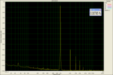
Dear OS,
- simulated distortion is 0.000175% @200W@8R (first 10 harmonics)
- measured THD+N using VP7723D only is 0.0018% (200W@8R, bw limit 80kHz)
- measured THD+N using DM 0.0012% (200W@8R, bw limit 80kHz).
Simulated distortion measurement is limited by the number of harmonics you define and real life measurement is (more or less) bandwidth limited.
The simulation doesn't include performance losses due to various other small thinks like
- pcb layout
- wiring
- crosstalk
- temperature
- component quality
So for "my" rule of thumb I would multiply the simulated THD results by > 10 to get more practically values if a circuit design simulates with ppm or sub ppm values.
BR, Toni
I think it's more important to understand WHAT about the simulation is inaccurate, then you can correct it and get better results, and understand more about your design as well. There are examples of sub ppm amps that had lower THD in real life, as well as examples with more distortion, so I think a rule of thumb for the accuracy of simulation is sort of a distraction from the normal process of R&D.
Of course you are right. Meant with "my rule of thumb factor" that this is only valid for my blameless project.I think it's more important to understand WHAT about the simulation is inaccurate, then you can correct it and get better results, and understand more about your design as well. There are examples of sub ppm amps that had lower THD in real life, as well as examples with more distortion, so I think a rule of thumb for the accuracy of simulation is sort of a distraction from the normal process of R&D.
The question: is it valid to compare two (partially different) circuits with different bjt models and to conclude the real life measurements from one project can be transferred as prediction for the other project?
I think it's more important to understand WHAT about the simulation is inaccurate, then you can correct it and get better results, and understand more about your design as well. There are examples of sub ppm amps that had lower THD in real life, as well as examples with more distortion, so I think a rule of thumb for the accuracy of simulation is sort of a distraction from the normal process of R&D.
I agree. If we have enough equipments, after implementation of the design, we must evaluate and tweak it. May be change components type or value, rearrangement the PCB layout or components. Usually manufacturing have a room with temperature controller, you can evaluate your design using target of temperature range. Typically, at the design process we make at least 3 steps prototyping until the final version for mass production.
BUT, this is DIY
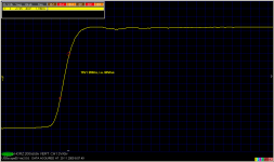
....CFA is capable of very high slew rate. VAS works in push-pull and can deliver current on demand.
Now the question: Do we need some kind of VAS transistors protection as in VFA?
I simulated IPS in isolation with no any VAS protection and with VAS protection. This IPS has SR of 250 V/usec with the VAS standing current of 6 mA. When protection is active SR drops dramatically to 94 V/usec in this case. It could be increase by choosing higher current level for the protection transistors, but then protection is not so good.
BR Damir
Attachments
Natural music signal would never request such high slew rate. Only test signals like dirac impulse, unit step, square and sawtooth do, but they have infinite spectrum.
Some people here argue that high slew rate is more musical(I know it is not supported by theory, and I don't have direct listening experiance) and the main advantage of the CFA over the VFA was high SR. If we go down with SR then it's simpler to make a VFA, with better DC stability. It is easy to make simple good sounding CFA, but then if we incorporate all needed protection then is not so simple any more. I know this is a hobby and if the amp was overloaded and something burned, it is easy to repair if one made the amp in first place, but the amp can take the loudspeaker with it and that is not good at all. Output relay or MOSFET is not my piece of cake, prefer all protection to be in the power supply board, or better on the same amp board(cap multiplier with current protection, DC offset protection and switch off in the case one side of the pus or minus supply was cut for some reason.
BR Damir
- Home
- Amplifiers
- Solid State
- CFA Topology Audio Amplifiers