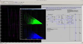
Attached a power supply simulation where you can check the effect of the snubbers during output load ...
Hi Toni
These values for primary inductance don't look correct.
We had a discussion about this before. LINK HERE.
I suspect this will then mess up some of the other values too, stray inductance is calculated from the primary inductance, I think.
I have a 240 V toroid power transformer out in the workshop that I will measure later.
We need better data on this.
But I also suspect it makes less difference than many people believe.
Your comparatively low value snubber resistors make sense to me.
Best wishes
David
Last edited:
Dear David,
your are right. Maybe the transformer model isn't correct but good enough to see the oscillation of the LC circuit and how it can be damped and what influence it has compared to other problems (EMI, RFI).
Better transformer simulation models are always welcome. I have my transformer model verified with this document: http://cds.linear.com/docs/en/lt-journal/LTMag-V16N3-23-LTspice_Transformers-MikeEngelhardt.pdf . This document helped me to understand my 650VA model comparing the turns ratio with inductance:")
BR, Toni
your are right. Maybe the transformer model isn't correct but good enough to see the oscillation of the LC circuit and how it can be damped and what influence it has compared to other problems (EMI, RFI).
Better transformer simulation models are always welcome. I have my transformer model verified with this document: http://cds.linear.com/docs/en/lt-journal/LTMag-V16N3-23-LTspice_Transformers-MikeEngelhardt.pdf . This document helped me to understand my 650VA model comparing the turns ratio with inductance:
See page 1: ... "Setting the turns ratio of the transformer is simply a matter of choosing the right inductor values. Remember, the inductance is proportional to the square of the turns ratio. In the example above, a turns ratio of 1:3 gives a 1:9 inductance ratio." ...
Real life measurements of power supply (without the extra snubbers) output signals are showing mostly the ripple voltage. Have to do a FFT analysis using my HP3585A if the rectifier triggered LC oscillation can be seen on the output.
BR, Toni
Last edited:
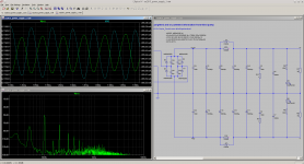
CRC snubber FFT comparison simulation
Attached a better simulation with and without extra snubber.
The bottom FFT (no extra snubber) shows a -115 db artefact at Vout+ (at diode output and before extra filtering) with exactly the LC oscillation frequency. (FFT simulation time range from 1s to 2s)
Need to be verified in real life using HP3585 if this oscillation is as small as predicted and hence negligible...
Attachments
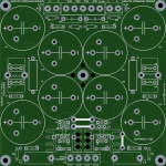
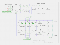
SA2013 V3.4.1 power supply
Now with added extra snubber. Schematics and pcb gerber files are free to use only for non commercial DIY projects.
WARNING: this circuit provides very high DC voltages and is therefore very dangerous and can be lethal. I am not responsible for any costs, damage and/or injury using these schematics. Do not use this schematics if you do not have the necessary experience and knowledge.
Have fun,
Toni
Attachments
...Need to be verified in real life...if this oscillation is as small as predicted
Probably quite difficult to predict accurately, need to model capacitor stray inductance, ESR, trace inductance etc. etc.
But I expect very low level - and then suppressed more by the amplifier Power Supply Rejection Ratio, perhaps 60 dB and possibly quite a bit more.
So I am unconcerned by attempts to find the "optimum" snubber resistor.
Your approach looks fine, just damp it heavily.
Best wishes
David.
Last edited:
Dear David,
many thanks for checking!
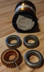
For those who want to use coils for better ripple rejection: I just have finished 1 of 4 coils. See attached picture. I'm using core material FT140-77 with 36 turns of 1.5mm enameled copper wire (wire length ~ 155cm). Measured 3.6mH. Simulation gives about 3mV rms 100Hz output ripple during small signal listening load.
many thanks for checking!
For those who want to use coils for better ripple rejection: I just have finished 1 of 4 coils. See attached picture. I'm using core material FT140-77 with 36 turns of 1.5mm enameled copper wire (wire length ~ 155cm). Measured 3.6mH. Simulation gives about 3mV rms 100Hz output ripple during small signal listening load.
Attachments
Dear David,
many thanks for checking!
For those who want to use coils for better ripple rejection: I just have finished 1 of 4 coils. See attached picture. I'm using core material FT140-77 with 36 turns of 1.5mm enameled copper wire (wire length ~ 155cm). Measured 3.6mH. Simulation gives about 3mV rms 100Hz output ripple during small signal listening load.
Surely these saturate at quite a low current?
Surely these saturate at quite a low current?
You mean it would be better to use other core material?
From Amidon datasheet:
Material 77 (μi = 2000):
Has high saturation flux density at high temperature. Low core loss in the 1 KHz to 1 MHz range. For low level power conversion and wideband transformers. Extensively used for frequency attenuation from 0.5 MHz to 50 MHz. Available in toroids, pot cores, E-cores, beads, broadband balun cores and sleeves. An upgrade of the former 72 material. The 72 material is still available in some sizes, but the 77 material should be used in all new design.
Has high saturation flux density at high temperature. Low core loss in the 1 KHz to 1 MHz range. For low level power conversion and wideband transformers. Extensively used for frequency attenuation from 0.5 MHz to 50 MHz. Available in toroids, pot cores, E-cores, beads, broadband balun cores and sleeves. An upgrade of the former 72 material. The 72 material is still available in some sizes, but the 77 material should be used in all new design.
You mean it would be better to use other core material
To get high inductance at high currents you need either a very, very big ferrite core or ferrite with an air gap, or an iron powder core ("distributed" air gap).
If you look at page 16 of this PDF:
http://ecee.colorado.edu/copec/book/slides/Ch12slide.pdf
You will see an equation that relates: core saturation flux density, magnetic path length, permeability (= relative permeability x permeability of free space) and number of turns, to saturation current.
For your toroid:
saturation flux density = 0.46 T (according to: http://www.amidoncorp.com/product_images/specifications/2-04.pdf)
path length = 90.2 x 10^-3 m (according to: http://www.amidoncorp.com/product_images/specifications/2-06.pdf)
permeability = 2000 x 4 x pi x 10^-7 H/m
number of turns = 36
Plugging the numbers in to the equation gives a saturation current of:
450 mA
Of course, this is assuming a very simple saturation model and in reality the inductor will start to saturate at a lower current (probably around 300 mA).
The range and quality of off-the-shelf inductors has improved significantly over the last few years. Why not just get something from Mouser?
Last edited:
To get high inductance at high currents you need either a very, very big ferrite core or ferrite with an air gap, or an iron powder core ("distributed" air gap).
...
Thx. Many new things to learn for a power supply ripple rejection ...
I have only limited knowledge using inductors so please forgive me if this is a stupid question: High DC bias current will now kill the inductance hence the ripple rejection - or only a high AC current?
Hi guys,
Toni,
Now that you have the secondary sorted out, what about the primary circuit? is there a soft-start ckt to limit inrush current?
Possible to put, the line entry socket/switch, primary fuse, filters, soft-start relay, etc, on the secondary pcb, makes wiring a lot easier.
Cheers
Rick
Toni,
Now that you have the secondary sorted out, what about the primary circuit? is there a soft-start ckt to limit inrush current?
Possible to put, the line entry socket/switch, primary fuse, filters, soft-start relay, etc, on the secondary pcb, makes wiring a lot easier.
Cheers
Rick
Last edited:
Thx. Many new things to learn for a power supply ripple rejection ...
I have only limited knowledge using inductors so please forgive me if this is a stupid question: High DC bias current will now kill the inductance hence the ripple rejection - or only a high AC current?
Sadly, high DC current will do it (kill the inductance), in much the same way that too high a DC bias voltage on a capacitor will kill the capacitor (the difference being that exceeding the max e-field in a capacitor will tend to kill the capacitor permanently, whilst an inductor can recover 100% if the max b-field is exceeded (assuming the current required to exceed the max b-field is lower than the current that will melt the wires!).
Thx! I will go for resistors ...Sadly, high DC current will do it (kill the inductance), in much the same way that too high a DC bias voltage on a capacitor will kill the capacitor (the difference being that exceeding the max e-field in a capacitor will tend to kill the capacitor permanently, whilst an inductor can recover 100% if the max b-field is exceeded (assuming the current required to exceed the max b-field is lower than the current that will melt the wires!).
Sadly, high DC current will do it (kill the inductance), in much the same way that too high a DC bias voltage on a capacitor will kill the capacitor (the difference being that exceeding the max e-field in a capacitor will tend to kill the capacitor permanently, whilst an inductor can recover 100% if the max b-field is exceeded (assuming the current required to exceed the max b-field is lower than the current that will melt the wires!).
OK - hopefully it would be only a loss of 10 - 20% or so for a maximum of 4A DC.
Just for understanding - is this document usable to calculate the max needed flux for a toroid?
http://www.amidoncorp.com/product_images/specifications/1-36.pdf
If yes, then the maximum flux density of a ripple voltage of 0.29 Vrms@100Hz using the FT140-77 core would be 2250 Gauss well below maximum flux density of 4600 Gauss. Or am I completely wrong?
You need to account for the flux generated by all current flowing in the inductor, not just the 100 Hz ripple component. There will be a significant DC component and this will saturate the inductor.
You need to account for the flux generated by all current flowing in the inductor, not just the 100 Hz ripple component. There will be a significant DC component and this will saturate the inductor.
As always: Thx!
Now its clear that using an inductor to reduce the ripple voltage here is more or less nonsense compared to the effect and price of 2 pieces 0.47R resistors ...
Is there anybody out there needing some pieces of FT140-77 cores?
Thanks for the link back Toni, nice work.Dear Rick,
have a look at post #686 and #670
I like it modular, so I can reuse pcb's for other projects.
and the code for the PIC,you have that going now? I have lots of atmel xmega code to share with you.
Enjoy your summer, it is really nice here now. 25-30C of late, tomatoes, peppers, lilies are flowering.
Cheers
Rick
Dear Rick,
thx! The PIC 16F690 with homebrew firmware is running in several different amplifier projects since 2012 without any problems.
Code-sharing isn't very easy between PIC and ATMEL but it is always good to share ideas and discuss them. For programming I use the open source SDCC compiler and a homebrew USB-PIC-Burner.
Now I know, where our summer makes holidays ...
In Tyrol we have currently 10 degrees and it's raining since days.
BR, Toni
- Home
- Amplifiers
- Solid State
- 2stageEF high performance class AB power amp / 200W8R / 400W4R