Brother printers are not very good for toner transfer. The toner they use is a different formulation than most others. I think the best results come from an HP with an OEM toner, though there are lots of others that likely work fine too.
I generally prefer the photographic method personally. I have a local print shop create the art on an imagesetter (totally opaque image) and buy pre sensitized boards. It costs more, and there is a little lead time on getting the artwork, but for a board or two the results are near perfect. Also the art can be used over and over.
It's not a high resolution pic, but this was the result I got from the photo method for my PeeCeeBee.
Last edited:
Terry,
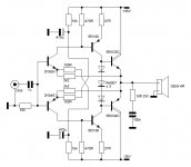
To the best of my knowledge there is no official BOM for Shaan's PeeCeeBee, but there is nothing special about the components either. You should be fine to follow the schematics for your values.
All resistors can be 1/4W metal or carbon film. The semiconductors are self explanatory. The 1uF decoupling capacitors can be film, X7R / c0g / np0 ceramics that physically fit and rated for at least 50V. The 2200uF need only be 6.3V aluminum electrolytic that fits and the 100uF (1000uF for some versions) should be 50V or greater if there is space.
Perhaps Shaan can mention what the maximum diameters for the capacitors are that fit on his board design. I can't speak to that since I went down my own path with the PeeCeeBee.
These little babies can be practically built out of a junk box, have a look and see what you have on hand that would work. You may have most of it already.
I have been searching but can't find it. Is there a BOM for Shaan's original PCB in post #1?
Hi still4given.
There isn't one yet. But here are the pin spacing for the passive parts.
All resistors- 0.4 inch
100uF caps- 0.1 inch
1000uF caps- 0.2 inch
1uF film caps- 0.2 inch
10uF input cap- 0.1 inch
Hope this helps.
The 100uF shown in the schematic in post 1 can be anything at least 100uF or greater, on mine it is a 1000uF rated for a full rail voltage, so 50V or better. Also the vogue thing to do is where the 1000uF is shown in the original schematic is to increase that to a 2200uF, and it can be a lower voltage unit too, 6.3V or a little higher is fine.
The amp isn't too critical on the parts used though the best and most consistent results not requiring any additional compensation seem to come from the BD139-16 / BD140-16 VAS and the BC550C / BC560C input transistor combination. The MPSA92 / MPSA92 (if that is what you meant, or even the 2N5401 / 2N5551 for that matter) could be used but have to be turned 180 due to the pinout differences and therefore can't be glued 'face to face'. They are also a significantly lower gain part, so not the best choice.
I'm curious to get your listening impression, mine positively blew me away.
Well I almost made it out of my junks drawer. Missing one BD140, the two 1000uf 50v electros and the BC550c and BC560c's. I have two drawers full of MSP**** to-92's.
How critical is the 100UF value. Can I take it up a bit? I have 220uF and 330uf.
Thanks, Terry
Hi Terry.
If you use the default 1000uF caps at the feedback node then upto 25V rated caps will be okay for the space on the board. If 2200uF is used [recommended] then use 16V rated ones, or even better, the 6.3V ones. Best to use a low voltage cap here.
The value for the 100uF cap is the minimum recommended as Jason mentioned. You can use anything upto 470uF if the cap fits on board while being 50V rated. I wouldn't recommend 1000uF as a higher value cap here is known to blow the 10R resistors in series with the 1N4007 diodes, sooner or later, due to sudden thermal shock while charging the large capacitor at power on.
Hi Guys,
OK, so I think I found caps that will work. A little large but by tipping them a little they will fit. So digging through some more drawers I found these transistors. Will any of these work?
BC559B
BC558BRL1G
BC546BZL1G
2SC2240
2N5401
2N5401RLRAG
2N5551RLG1G
MPS8099
MPS8599
MPSA18RLRPG
MPSA56RLRA
MPSA06RLRAMPSA56
MPSA42RLRAG
MPSA29RLRA
MPSA92
Also, I have these in to-225 cases
Will these work in place of the BD139/140? I have lots of the 139's but not enough 140's.
MJE340
MJE350
Hi Guys,
OK, so I think I found caps that will work. A little large but by tipping them a little they will fit. So digging through some more drawers I found these transistors. Will any of these work?
Let's go through what you have on hand...
Correct pinout and from the right family tree but a little light on the Vceo rating at 30V. No compliment listed.BC559B
BC558BRL1G
Again from the right product family and more desirable with a 65V Vceo, but you don't list its compliment.BC546BZL1G
This has the wrong pinout, nor do you list its compliment.2SC2240
Of this batch, they have a reversed pinout from the BC5xx devices but could be used in their respective complimentary pairs. Of these the MPSA06 / MPSA56 and MPS8099 / MPS8599 seem to be a 'best fit' but still a compromise. These can't be well coupled thermally as they won't be face to face on assembly.2N5401
2N5401RLRAG
2N5551RLG1G
MPS8099
MPS8599
MPSA18RLRPG
MPSA56RLRA
MPSA06RLRAMPSA56
MPSA42RLRAG
MPSA29RLRA
MPSA92
I'm sure they would work but I can't say how well. These are sometimes used as VAS transistors but aren't regarded as being a desirable for the task.Also, I have these in to-225 cases
Will these work in place of the BD139/140? I have lots of the 139's but not enough 140's.
MJE340
MJE350
The best transistors for this build are just pennies each and readily available. I'd personally use what you have now to get a feel for it and order some of the correct ones and upgrade it when they arrive. Ultimately up to you.
Thanks so much for all that detail. I will just get the right ones. I did want to learn though so I really appreciate you effort. I'm not in a huge hurry, just like to use what I have when I can. I probably have over 50 each of the parts I listed.
A friend offered to send me the right transistors so I'll go that route. I don't have another Mouser order anytime soon and I hate paying their shipping on small orders. Sure wish I had a real electronics store nearby. All we have here is Radio Shack and they are all but out of the electronic parts business.
Shouldn't bee too long before I have the little sucker singing.
Blessings, Terry
Darlington VSSA
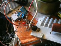
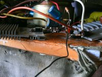
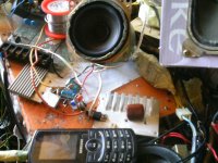
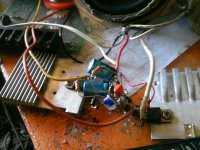
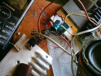
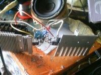
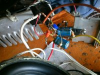
Here's my version of this amp,but I use darlingtons instead mosfet's.
I make 3D prototype,and complete it in about half hour
It's biased in class B but sound is very good
Input stage-2mA
VAS-12mA
Out-0mA
It works without any compensation.
I changed 100R to 22R,for more gain.
Instead Roff i change one 15k resistor to 12k + 5k pot.
Here's my version of this amp,but I use darlingtons instead mosfet's.
I make 3D prototype,and complete it in about half hour
It's biased in class B but sound is very good
Input stage-2mA
VAS-12mA
Out-0mA
It works without any compensation
.I changed 100R to 22R,for more gain.
Instead Roff i change one 15k resistor to 12k + 5k pot.
Attachments
-
 PTDC0003.JPG554.6 KB · Views: 566
 -
 PTDC0004.JPG573.6 KB · Views: 497
 -
 PTDC0006.JPG581.2 KB · Views: 469
 -
 PTDC0007.JPG536.8 KB · Views: 417
 -
 PTDC0008.JPG536.4 KB · Views: 393
 -
 PTDC0009.JPG523.4 KB · Views: 152
 -
 PTDC0010.JPG553.2 KB · Views: 136
 -
 PTDC0011.JPG497.7 KB · Views: 134
 -
 PTDC0013.JPG529.1 KB · Views: 158
 -
 BD amp..JPG46 KB · Views: 368
Last edited:
Here's my version of this amp,but I use darlingtons instead mosfet's.
I make 3D prototype,and complete it in about half hour
It's biased in class B but sound is very good
Input stage-2mA
VAS-12mA
Out-0mA
It works without any compensation
I changed 100R to 22R,for more gain.
Instead Roff i change one 15k resistor to 12k + 5k pot.
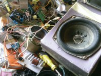
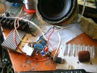
Wow, I'll have to show your pics to my wife so she'll get off my back about cleaning up my work bench.
Very cool!
Hi Acca. 
Your job is wow! I love the mess with those hanging parts and am amazed that you made it work without any problem.

Darlingtons are nice, but due to positive tempco and low fT they were avioded in the first place. I suggest you use a Vbe multiplier with them and fix the extra transistor to the main heatsink.
Please use the VSSA thread or the FET-hex Explendit thread to post your layout as this thread is focused only on Lateral FET designs.
Thanks.
shaan
Your job is wow! I love the mess with those hanging parts and am amazed that you made it work without any problem.
Darlingtons are nice, but due to positive tempco and low fT they were avioded in the first place. I suggest you use a Vbe multiplier with them and fix the extra transistor to the main heatsink.
Please use the VSSA thread or the FET-hex Explendit thread to post your layout as this thread is focused only on Lateral FET designs.
Thanks.
shaan
...only you and shaan who make point to point of this amp
No. Acca took it one level higher.
I used a veroboard, too easy.

Wow, I'll have to show your pics to my wife so she'll get off my back about cleaning up my work bench.
Very cool!
I must show you my workshop - Home
- Amplifiers
- Solid State
- PeeCeeBee