Hey guys
I will soon be building V1.4 of the original SSA. Schematic is attached.
I will be using KSC1845/KSA992 for Q1-Q6 due to the ability to make matched pairs. I have had no success matching medium power VAS transistors so far.
I would like to run the VAS at 5ma. 10mA will probably cook the VAS transistors.
Is the VAS current set by VR1? If I set the VAS at 5mA what do I change to get the outputs to bias at 130 mA?
http://www.diyaudio.com/forums/atta...57681-simple-symetrical-amplifier-design1.pdf
...as far as I can tell, the main source of noise that I can see on my venerable Tektronix 'scope is the power supply, and second, EMI coupled from the inexpensive toroidal transformer I am using in my test setup, and its leads. This can be seen by comparing the output when using my bench supply.
The most sensitive point is the twisted pair connection from the back panel to the input terminal on the board. This can be seen on the scope, by moving the input leads back and forth by hand - closer to the transformer, the noise on the output grows. Further away, it shrinks.
You are absolutely correct. The input cable is indeed sensitive to EMI.
Some funny look-back:
Long ago when I used only carbon films I encountered noise in almost every amp I had built. All LTP quasi-comp type. The ready-made boards available in the local market was just as bad as my diy ones, and sometimes, worse. The noise I have encountered through the speaker in most of those cases was white noise, in a few hum, in a very few ground loop, and in one, HF oscillation noise through my AM receiver, my radio was dead. 😀.
Obviously the input cable was dangling over the transformer to reach the volume control. I had little understanding/knowledge of the EMI stuffs, used to think that cabling procedure inside the cabinet is no different than the cabling for mains, and had strange ideas like the -ve PS rail is the 'second ground'

 . I was slowly almost reaching the conclusion that making a silent amp every time happens only in the factory, and in home it's just pure luck. Silly me.
Yeah of course there was people around me who were even below my level, my 'diy' pals, with whom I had made a lot of fun projects to show in the school's science exhibition. One of them once got too excited, rolled uncoated earthing wire on a piece of steel rod and decided to make an ultra-magnet out of it with the help of the mains AC, a magnet that could attract from at least 10 meters, effect of too much super-human stuff on teevee [he is an animator now, naturally]. He says he saw an angel in front of him as he pushed the switch. Next day the electricity guys came and replaced the 30A mains fuse wire.
Sorry for the off-topic. We were only fifteen. 🙂
...the original SSA. Schematic is attached.
Oho.
Nice. Someone wants to taste the original thing...
Hi woofertester. Go to the following thread and do post your progress there... Will be great.

THE SSA THREAD
cheers
shaan
Hi Jaagut,Built PeeCeeBee using John Bali PCB layout.
Parts used:
BC547B/BC557B because BC560C was not available (I think this product was discontinued and replaced by BC556C?)
all 1uF caps, input cap were all non-polar caps (JakeC brand)
all resistors were regular carbon resistors
rail DC was +/-25V.
first on, i burned 10R resistor while the other 10R became 6.6R😡 found the problem. cause was swapped input transistors.
second on, output DC was somewhat unstable, so i put VAS compensation caps of 24pF.
third on, offset DC was high at 82mV. i tried to parallel 15k with 150k, offset DC became -82mV. i tried another value 330k, and the offset was 2 mV. 🙂
satisfied with above and was pretty stable.
sound was clean and loud. i liked the bass, mid, and high and suited my taste.🙂
Very nice, thanks for try my layout 🙂
So we must use compensation caps there...
Do you want to try BD139-140 so we don't need that caps, must try it
You make PeeCeeBee by hand drawing too I see, great 🙂
use bigger size marker & refilling the ink so you will have better finish
Regards
You are absolutely correct. The input cable is indeed sensitive to EMI.
Yes, there are rules that must be obeyed when building amps.
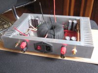
I tried to brake those rules and made very small enclosure, smaller then sheet of paper (290 x 190 mm). Although all components fit inside, I didn't get good result.
Input cap is next to trafo, input and output leads go together over power supply, enough for bad result.
To avoid noise I ordered bigger heatsinks and I'll make standard (17") width enclosure, so components will be at bigger distance.
Then I'll again enjoy in beautiful sound of this wonderful amp.
Attachments
@dobrivoje:
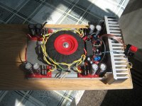
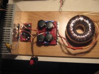
My test chassis is not much bigger inside than yours, with an ordinary toroidal transformer, not shielded. However, I am using a twisted/shielded cable for the inputs, with shield connected to chassis in the back. My power supply is highly filtered, but also quite small. So, you do not always need a big chassis (even though it is nice to have).
The mains wiring is normally twisted, and shorter, but the picture was taken when I was doing some testing on the transformer, so I needed longer wires.
The white/black wires are AC. Grey cable is input. Blue wires are output and return. Transformer primary and secondary connections are at the front, and the extra wire length I needed for the test is tucked under the transformer. One of the modules from LC's group buy is on the left, shown for scale.
Attachments
Hi jaagut.
Congrats! Nice build.😎
We will be delighted to have a detailed review on the sonics of your boards. Especially because carbon resistors are used throughout the board and low noise input transistors weren't used. How good the soundstage is with a stereo setup is one of the most important points and also the reason why one amp sounds better than another. Have you compared its sound with other amps yet? What do you feel different/better or different/worse(if any) with PeeCeeBee?
Sorry for so many Qs. 😉😀😉😛
Please give it a good week-long listen and kindly report afterwards.
Thanks.
shaan

Thanks!
Yes, in due time, 🙂 I only have weekends to tinker and listen to my DIY amps. I am amazed at how good is the sound for this very small 6-trans amp!
This is an example of an outstanding minimalist amp!
Hi Jaagut,
Very nice, thanks for try my layout 🙂
So we must use compensation caps there...
Do you want to try BD139-140 so we don't need that caps, must try it
You make PeeCeeBee by hand drawing too I see, great 🙂
use bigger size marker & refilling the ink so you will have better finish
Regards
Hi John,
Thanks for your layout, the fastest way to implement a PeeCeeBee! 🙂
My board used BD139/140, I don't know but after putting caps, the DC became steady and not fluctuating.
Good one, I will definitely try your tip!
Thank you, PMI.
I also got some advice from Juma and I'll try to fix the problem.
You have three inches between trafo and amp's input. I have ... khm ... zero.
I also got some advice from Juma and I'll try to fix the problem.
You have three inches between trafo and amp's input. I have ... khm ... zero.
...but after putting caps, the DC became steady and not fluctuating...
Oscillation can result from a number of things including electrically floating metallic surfaces near sensitive processing areas on the board. In your case, I suspect it's the clamp that binds the input transistors together. Looks like it is not grounded. This particular node of the amp has the most sensitivity to EMI/RFI etc. and extreme care should be taken to make sure that there is no such interference source near the input BJTs. A good idea is to either use a zip tie or a tiny drop of superglue to bind them, or even better, connect the existing metal clamp to signal ground with a small wire, which will provide great immunity to EMI/RFI.

shaan
Also, see this post by nicosokey. It's possible to make a stable PeeCeeBee without miller caps.
PeeCeeBee 500KHz squarewave scope test
PeeCeeBee 500KHz squarewave scope test
It is very good idea 🙂 why I miss that 😕Oscillation can result from a number of things including electrically floating metallic surfaces near sensitive processing areas on the board....
A good idea is to either use a zip tie or a tiny drop of superglue to bind them, or even better, connect the existing metal clamp to signal ground with a small wire, which will provide great immunity to EMI/RFI.
shaan
I use aluminium tape & not grounded
so I & Jaagut really need to ground that the little piece of metal to ground
I will try to find some copper so it can be soldered to ground 🙄
I just don't remember where I put the spare matched pair input 😀
now it's searching time
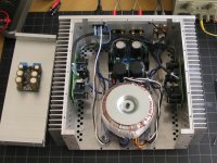
I believe that you will find that that long heat sink will not be effective beyond about 1.5" past the last semiconductor in either direction. This is for the same reason you can use the handle on an iron skillet. Different magnitudes of heat but the same concept. If it were square instead of long it would be much more effective.
I believe that you will find that that long heat sink will not be effective beyond about 1.5" past the last semiconductor in either direction. This is for the same reason you can use the handle on an iron skillet. Different magnitudes of heat but the same concept. If it were square instead of long it would be much more effective.
Hi Aanoit,
welcome to the PeeCeeBee world

That heat sink is only for test, I know how hot they are 😎
this is my first try: single pair one
Will you make any of these PeeCeeBee?
Some space is obviously required, but it is hard to tell how much or how little. Can you hear any noise from the speaker? If you can, the easiest thing to do is just make longer wire pairs, and move them away until the output is silent. That gives you a general idea of how much emi there will be in a chassis.Thank you, PMI.
I also got some advice from Juma and I'll try to fix the problem.
You have three inches between trafo and amp's input. I have ... khm ... zero.
Some space is obviously required, but it is hard to tell how much or how little. Can you hear any noise from the speaker? If you can, the easiest thing to do is just make longer wire pairs, and move them away until the output is silent. That gives you a general idea of how much emi there will be in a chassis.
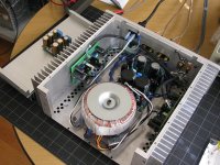
That's what I'm talking about.
I hear some buzzzz from speaker.
When amp was on a board, I heard only "sound of silence".
Even now, when I move amp an inch or two away from trafo and divide input and speaker leads, there is no buzz.
I hope this weekend I'll make progress and solve the problem.
Attachments
Hi Masood...
Use BD139-140 instead any higher speed transistor so no need any compensation caps.
The speakers just for fun 😀 has build it long time ago
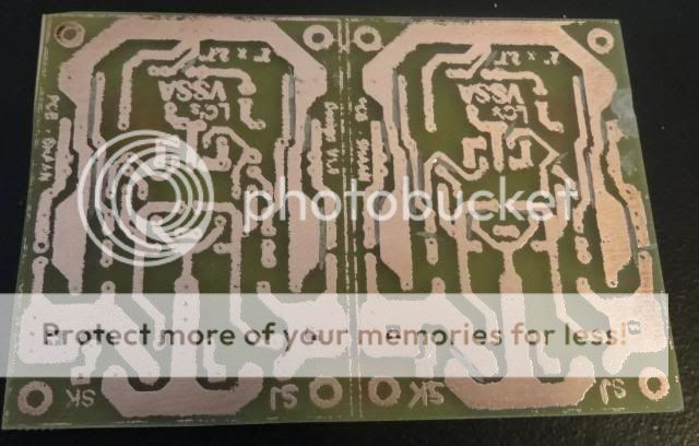
So here the PDF but no value cos I don't have it 😎
please send me PM if someone want the .dip file(I use diptrace)
board size : 100mm x 64mm
I need someone that build it too 🙂😉
Hi John,
Does the bottom view need to be mirrored for iron transfer?
Thanks, Terry
Hi Terry,Hi John,
Does the bottom view need to be mirrored for iron transfer?
Thanks, Terry
Yes you must print it mirrored for toner transfer...
bottom view is what it look from copper side,
for input transistor the nearer from input header is PNP & I will try 2SA-SC combination on my next build...
Happy building 🙂
Hi Dobrivoje,That's what I'm talking about.
I hear some buzzzz from speaker.
When amp was on a board, I heard only "sound of silence".
Even now, when I move amp an inch or two away from trafo and divide input and speaker leads, there is no buzz.
I hope this weekend I'll make progress and solve the problem.
I have same problem if the transformer is too close...
that's why it is still naked 😀
Try lift the transformer like PMI did, use non metal/non inductive spacer if that can solve the problem
Last edited:
Hi John,
I only have acrobat reader right now and had a tough time getting the transfer to work. I have a Brother laser printer and it doesn't work very well. I just decided to go with the first design. It took 6 tries with the iron to get a workable transfer and it took a lot of touch-up. They don't look to good but a little work with the dremmal and I think it will work ok. I have to get some parts ordered.
Blessings, Terry

- Home
- Amplifiers
- Solid State
- PeeCeeBee