GREAT INFORMATION!
Thanks MOOLY!
A trap for young players there! So...
P1/Ground measures slightly negative voltage. Negligible amounts.
P2/Ground measures 6.7V.
So I guess we have now narrowed it down to the RIGHT Channel, according to the manual at least.
There's progress, right there!
Thanks MOOLY!
A trap for young players there! So...
P1/Ground measures slightly negative voltage. Negligible amounts.
P2/Ground measures 6.7V.
So I guess we have now narrowed it down to the RIGHT Channel, according to the manual at least.
There's progress, right there!
Could wildly inaccurate DC OFFSET settings be the culprit?
One thing that has always made me curious, is that this amp barely gets warm during either CLASS A or CLASS AB operation. This seems highly unusual given the way CLASS A works - and based upon the amount of highly efficient cooling engineering that this machine has been endowed with.
All begging the question:
As I have never previously attended to the DC OFFSET (nor the BIAS CURRENT), is it possible that these adjustments are so far of the mark that it is causing these DC Protection Circuit problems?
(Just a thought?)
Anyways, the LEFT CHANNEL DC OFFSET is now perfect at at solid .1DC. The RIGHT CHANNEL DC OFFSET is sitting at a solid - and undesirable - 6.7V.
Something in that right channel is very wrong...
Last edited:
OPAMPS 4558D Measured...
PITBUL
OPAMP 4558D (Assume it's the LEFT CHANNEL, from the balanced results) measured: -
LEG 1: .87V
LEG 7: .87V
OPAMP 4558D (Assume it's the RIGHT CHANNEL, from the unexpected results) measured: -
LEG 1: -13.17V
LEG 7: -7.54V
Seems like the latter OPAMP is not happy. Yet it shows no sign of wear, overheating or damage...???
Last edited:
Bias adjustment will have no effect on DC offset.
You would have to look at all the voltages on the opamp for it to make sense but I would doubt there is an opamp issue providing the supplies to it are correct (on pins 4 and 8).
Jump in at the deep end...
Switch the amp OFF and do a quick resistance check on the four 0.22 ohm resistors located on the emitter of the output transistors. Is any pair open circuit?
Also check the output transistors by measuring resistance from collector to emitter. Are any short circuit.
If you are novice to electronics repair, I would suggest that you try to replace opamp on the right channel and after you do replacement adjust vr3 or vr4 (do not know which one coresponds to replaced opamp) to correct value on the output (0 V of the right channel).
If that doesn't help, you should check other components in the amplifier by measuring good amp channel with bad one. Maybe you should recap your amp, how old it is?
If that doesn't help, you should check other components in the amplifier by measuring good amp channel with bad one. Maybe you should recap your amp, how old it is?
I would say those presets are simply to trim the opamp bias currents. Normally a DC servo would use a FET opamp rather than a 4558 type.
The range of the preset will be minimal... look at the resistor values from the wiper of the pot. Its acting via a 10k across a 100 ohm.
Its really in place of an offset null adjustment for the opamp.
The range of the preset will be minimal... look at the resistor values from the wiper of the pot. Its acting via a 10k across a 100 ohm.
Its really in place of an offset null adjustment for the opamp.
Hi SONDEKNZ
Do you have the service manual? If not, you can download from the following link, once you have registered;
Avance Z501 - Manual - DC Stereo Power Amplifier - HiFi Engine
The manual explains how to set the dc offset (and bias), you adjust the trimmer pots on the driver board to adjust the dc offset. If you cannot adjust the faulty channel to around +/- 0.1V there, you have a problem.
You can measure from ground to the following points on the output board, which are the inputs from the driver board;
U1 & U2 should be around +1V
D1 and D2 should be around -1V
If you measure anything excessive here, it is likely that you have a problem on the driver board. Go around that and check dc measurements as they are indicated on the schematic.
This way, you can at least narrow down the fault area.
Good luck!
DEFINITELY PROBLEMS IN THE RIGHT CHANNEL...
Thanks DRUIDAUDIO
I have the manual already and have been working my way through it, trying some of the suggestions below.
There is no doubt that there is an issue in the RIGHT CHANNEL; it's now just about trying to find the source of the problem.
In line with suggestions from PITBUL and MOOLY below, I'm going through and measuring resistance in most components now, in the hopes that I can find something obviously faulty.
DC OFFSET and BIAS CURRENT settings will need to wait until the issue is resolved.
Thanks for sticking with me on this; these amazing amps are definitely worth all the effort!
Remember that its not normally possible to get accurate resistance measurements of components in circuit... very low value resistors and short circuit semiconductors excepted.
I would check those parts I mentioned earlier and then do a few careful voltage checks.
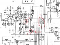
The diagram isn't terribly clear so hope this makes sense. I've numbered a few things.
1/ Check this 39k is OK. It's typical of a part that would fail, a high value resistor that sees high voltage. If it is as hot as the other channel its probably OK. If not then lift one end and measure it.
2/ Check there is around 1.8 volts across this diode combination.
3/ Check there is around 1.2 volts across this resistor.
Across means putting one lead on one end and the other lead on the other end") and not measuring to chassis.
and not measuring to chassis.
4/ What voltage do have on points U2 and on D2?
I would check those parts I mentioned earlier and then do a few careful voltage checks.
The diagram isn't terribly clear so hope this makes sense. I've numbered a few things.
1/ Check this 39k is OK. It's typical of a part that would fail, a high value resistor that sees high voltage. If it is as hot as the other channel its probably OK. If not then lift one end and measure it.
2/ Check there is around 1.8 volts across this diode combination.
3/ Check there is around 1.2 volts across this resistor.
Across means putting one lead on one end and the other lead on the other end
and not measuring to chassis.4/ What voltage do have on points U2 and on D2?
Attachments
If you don’t have them already, it is highly advised to get some of the small, clip on test leads so you can only touch the amp when it has been allowed to power down and also have the big capacitors discharged.
While this can be a personal safety benefit, it is more likely that you will slip a bit with a hand held test probe and cause damage.
Then you can check the values as shown on the schematic to see if the power is the same on both channels in the same places, like the diodes that were mentioned above.
Safety First!
PHASE - Thanks for considering my safety and the potential damage caused by uninformed "poking around". Appreciated.
(I am looking into these safety clips now...)
Meanwhile, I was trying to understand exactly what you mean and how I can test for value readings in the circuit, if you are suggesting I first power-down the amp and fully discharge the (massive) power supply caps?
I guess you are referring to measuring individual passive components - in isolation, right?
Mooly has just mentioned that there were a couple things to check, that would be a start.
Usually when you are lucky enough to have a functioning channel to check against, you have both the risk of trashing that one while probing, along with the benefit of having a reference.
Usually when you are lucky enough to have a functioning channel to check against, you have both the risk of trashing that one while probing, along with the benefit of having a reference.
Preparing to throw in the towel...
Well guys, (I assume you're all gents...)
I want to thank you for all of your efforts to help me here. Appreciated.
Sadly, I'm no further ahead and I'm fast running out of ideas.
One big challenge for me here, is that (as I understand it) many of the passive components - that could potentially be faulty - need to be taken out of the circuit just to be tested. With dozens of tiny resistors and diodes everywhere, I'm afraid that I'd be doing more harm than good, attempting this. Moreso, knowing that in doing so, I would be disturbing 99.9% perfectly good, operational componentry.
The other challenge is just finding the stuff you guys are asking about. It's probably pretty routine for a seasoned professional to zero-in on particular components, but as a newby, I'm having a lot of trouble relating the schematic - and your suggestions - to what's actually on the boards.
So, I'm at the point where I've gone as far as possible on my own. I think it's time to enlist some paid help to sort things out.
As an aside, one of my pet hates is great threads that never get concluded. (I know there are often good reasons why...) Anyways, I will try to round off the thread with an outcome, in the hopes that someone can learn something from our little adventure here.
Stand-by for more info with photos, if possible.
Thanks again folks - with particular thanks to PITBUL and MOOLY for the very practical test suggestions.
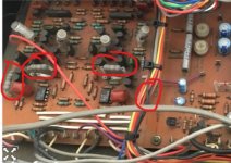
Before doing anything, just check these four resistors. I actually hadn't spotted the other pair when I looked at the circuit. These are metal oxide resistors and they run hot which means they can fail by going high in value or open circuit.
Quick 'engineer mode' test check is just to see if they all run about as hot as each other
Quick 'engineer mode' test check is just to see if they all run about as hot as each other
Attachments
Another quick check of the 04 x 39K Resistors...
Thanks for sticking with me on this, Mooly
As you will know, these Resistors are specified for 39K each.
(By the way, this amp is loaded with these METAL OXIDE Resistors, all of which seem okay, as follows...)
Measured in circuit - across each Resistor - with the amp completely powered down and drained, they each measure around 38K. Within .1K of each other.
Seems like they are okay.
I have poured over every resistor several times and measured in this way.
Sadly, no last minute "AHA!" moment at this end.
As an aside, can you explain what you mean by "Quick 'engineer mode' test check is just to see if they all run about as hot as each other..."
The reason I ask is that I can't get them hot to check as the Protection Circuitry has locked me out. The amp will not power up at all.
Last edited:
Repair approach???
Another question I would like to ask the panel...
In the event that it was (say) one of the 39K resistors that was crook, would a normal repair require removing the entire board to access the underside?
Or what most competent engineers attack from the top of the board and try to squeeze their iron in between the forest of other components and wires?
Understanding this will help me to know what to expect from my paid help.
Entire PRE-DRIVER BOARD Right Out to repair - Approach?
In the event that the entire PRE-DRIVER BOARD had to come out to replace a failed component, I had theorised that I would probably remove the 6 (gold) screws retaining the whole control-panel and simply desolder the board from the main fuse.
In this way, I figured that I could remove the board retainer nuts and "hinge" the board up at the front - complete with the entire control-panel - whilst the board remains largely connected as is; and in this way, access the underside of the board to effect a quality repair.
It just doesn't seem that hard to me - and may help me causing more damage with a top-down repair.
Am I making too big a job of it? Am I mad?
- Status
- This old topic is closed. If you want to reopen this topic, contact a moderator using the "Report Post" button.
- Home
- Amplifiers
- Solid State
- A501 / Z501 Luxkit Amplifier schematic