Those using G5LE type mech relays wonder if something like this would be drop in replacement with SSR. The DIYA store protect uses G5LE type SPDT relays.
Does anyone know if VOM1271 requires regulated or ripple free supply. This follows discussion here.. post no. 545 / 547 onwards
Speaker Turn On Delay and DC Protector Board Set (V3)
Does anyone know if VOM1271 requires regulated or ripple free supply. This follows discussion here.. post no. 545 / 547 onwards
Speaker Turn On Delay and DC Protector Board Set (V3)
Attachments

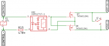


Ive used both the VOM1271 and the TLP191. The pin numbering is different, but they are actually pin compatible.
I run the diode current at about 15 mA and switch a large power mosfet (high input capacitance) SSR at about 80 us
I run the diode current at about 15 mA and switch a large power mosfet (high input capacitance) SSR at about 80 us
Thanks Bonsai,
I wanted to know if these chips require regulated supply or just rectified and smoothened (with a cap) is also ok?
I wanted to know if these chips require regulated supply or just rectified and smoothened (with a cap) is also ok?
No regulated supply required Prasi.
The LED switches the internal mosfet on with a photo-electric effect so on the output pins you get a current (15uA on the VOM1271 and 25uA on the TLP191).
You need to push about 10 to 15 mA through the LED.
When you select you mosfets for the SSR, make sure they are Logic Level devices - so fully on at about 5 V gate to source voltage. Standard Level devices have a higher threshold.
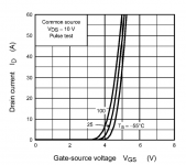
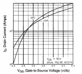
The Vgs scales are different! But they both look good. My preference after a quick look would be the 1st one.

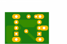
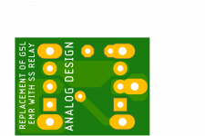
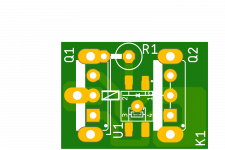
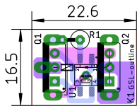
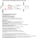
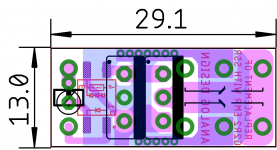
Hello all, here is something based on above suggestions by Bonsai, the design of pcb for G5LE type EM relay replacement with SSR. Its in a panel of 4 x4, so if one orders 5 pcb, one will get enough to make 20 SSR. I purposely kept smaller panel so that shipping costs are lower. JLCPCB, I think doesn't charge extra for panelized designs also...
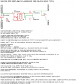
Also attached is the sch with few notes as I could gather from my understanding of Bonsai's article, so that even someone new to DIYA can easily build one.
Also attached is the sch with few notes as I could gather from my understanding of Bonsai's article, so that even someone new to DIYA can easily build one.
Attachments

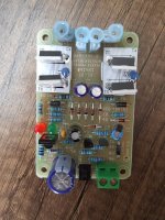
If anybody is interested in building PMA´s circuit of post #288 (picture in #724),
I have 2 PCBs left for 5$ each plus shipping.
I have 2 PCBs left for 5$ each plus shipping.
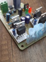
What are you using in the position of optocupler?
I see a photovoltic opto used in this position at all the circuits that i see.
I see a photovoltic opto used in this position at all the circuits that i see.
PMA uses a 4N33, I used a 4N32 in that spot because that´s what my distributor had available.
Last edited:
I have a doubt or 2, glad if some one can answer.
1. Does SSR needs speaker pole to be grounded, my understanding is that since no arc is involved during fault, there no need to.
2. refering datasheet of G5LE page 3 of https://omronfs.omron.com/en_US/ecb/products/pdf/en-g5le.pdf
can we connect pol1 to speaker, pole 4 to ground and pole 3 to amp?
1. Does SSR needs speaker pole to be grounded, my understanding is that since no arc is involved during fault, there no need to.
2. refering datasheet of G5LE page 3 of https://omronfs.omron.com/en_US/ecb/products/pdf/en-g5le.pdf
can we connect pol1 to speaker, pole 4 to ground and pole 3 to amp?
I'm not really following you on that one. A mechanical relay and an SSR both have the 'in' and 'out' terminals floating so they can be used however you wish within the constraints of isolation voltage between coil and contact (or opto isolation voltage for SSR) and 'withstand' voltage between 'in' and 'out' which is flashover voltage for the contact and FET voltage rating for the SSR.
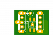
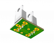
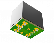
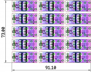
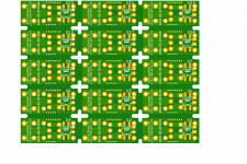
Here is something I made for a friend who uses G2R relays
panel size is 3 x 5 pcbs. so 5 pcbs will give 75 relay pcbs.
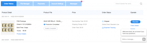
I had placed order for my earlier design using G5L relays in panel form 2x2. JLCPCB did not charge anything extra for panelized design. So USD 8 including shipping for 10 panels or 40 relay pcbs.😀 amazing!
regards
prasi
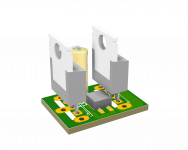
PS: the right side mosfet can be bent backwards and made to rest on the pcb with some insulation material on its tab (if one feels the fets are too close together)
panel size is 3 x 5 pcbs. so 5 pcbs will give 75 relay pcbs.
I had placed order for my earlier design using G5L relays in panel form 2x2. JLCPCB did not charge anything extra for panelized design. So USD 8 including shipping for 10 panels or 40 relay pcbs.😀 amazing!
regards
prasi
PS: the right side mosfet can be bent backwards and made to rest on the pcb with some insulation material on its tab (if one feels the fets are too close together)
Attachments
-
 SCH.png51.2 KB · Views: 578
 -
 G2R-1-E SSR RELAY - PANEL-TOP.png128 KB · Views: 565
 -
 G2R-1-E SSR RELAY - PANEL-STUFFING.png78.9 KB · Views: 518
 -
 G2R-1-E SSR RELAY - PANEL-BTM.png148.7 KB · Views: 524
 -
en-g2r.pdf3 MB · Views: 237
-
GERBERS-G2R-1-E SSR RELAY - PANEL_2021-05-24.zip560.9 KB · Views: 140
-
 JLCPCB-ORDER.png88.5 KB · Views: 504
 -
 LAY.png26.1 KB · Views: 298
Last edited:
Hello all, here is something based on above suggestions by Bonsai, the design of pcb for G5LE type EM relay replacement with SSR. Its in a panel of 4 x4, so if one orders 5 pcb, one will get enough to make 20 SSR. I purposely kept smaller panel so that shipping costs are lower. JLCPCB, I think doesn't charge extra for panelized designs also...
Also attached is the sch with few notes as I could gather from my understanding of Bonsai's article, so that even someone new to DIYA can easily build one.
Here is something I made for a friend who uses G2R relays
panel size is 3 x 5 pcbs. so 5 pcbs will give 75 relay pcbs.
I had placed order for my earlier design using G5L relays in panel form 2x2. JLCPCB did not charge anything extra for panelized design. So USD 8 including shipping for 10 panels or 40 relay pcbs.😀 amazing!
regards
prasi
PS: the right side mosfet can be bent backwards and made to rest on the pcb with some insulation material on its tab (if one feels the fets are too close together)
With regret I have to inform that I have found an error with both PCB designs, basically with coil polarity in the schematic is other way round (in my eagle library). So please dis-regard both of them.
if moderators could delete both the posts, that would be nice. Sorry for inconvenience. 😱
I was wondering, how many MOSFETs can be run from a single VOM1271?
As much as you want. Only the turn on/turn off time became longer as you add more devices.
With regret I have to inform that I have found an error with both PCB designs, basically with coil polarity in the schematic is other way round (in my eagle library). So please dis-regard both of them.
if moderators could delete both the posts, that would be nice. Sorry for inconvenience. 😱
prasi, in this post I can't see any errors... all connections are OK, even the resistor on the LED's cathode is OK, it is a current limiting element after all... so polarity should be OK too. In the other post, sounds like you have flipped VOM1271, thu this can be fixed easily.. I don't see any point deleting those posts, posting a fix solves the issues in this post.. any member using someone's else design, should be aware they are supposed to review the design after all.
- Home
- Amplifiers
- Solid State
- Output Relays