I use DPDT relays and cut both lines to the speaker.
I suppose that might be helpful if the relay actuators have different. If they share the bit that moves, then technically, if one contact were going to weld shut it would hold the other contact in place too.
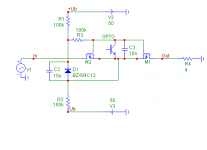
Attached is fully functional circuit. "OPTO" is open colector output of optocoupler driven from protection circuit...Any thoughts... Would it work ?...
Attachments
Hi all,
Maybe, maybe not.
I would suggest that there may be a need for a suitable small circuit board that can be retro-fitted to existing designs or used in pure DIY Builds.
As I am familiar with the problems caused by output relays I have been using crowbar relays for speaker protection for decades. This removes the relay from signal current path completely during normal operation and protects the speakers.
However clearly, if there is a fault, the relay will often melt shut and the severity of damage to the output stage will be increased. It has however served well and I only had the output protection trigger in anger a few times since the 80's, when it did the internal results tended to be quite spectacular, based on the post mortem, but I never fried a speaker from blowing up Amp...
As I am currently again mucking about with a general style solid state Amp (mainly a research platform) I have also been looking at the whole relay question again. This Amp will use fairly expensive lateral mosfets and be somewhat experimental (so I'm expecting the odd protection triggering), so perhaps I may wish to avoid the crowbar relay approach this time...
The approach using Mosfets seem decent based on the measurement results, though not as good as a high quality signal relay but better than the bad examples Bob Cordell shows in his book.
My suggestion for the "diya speaker protection board" would be to use a combination between a solid state (FET) switch and a mechanical switch (high quality signal relay), with interlocked and precisely managed timing.
The idea is that after the FET switch is fully engaged the signal relay can then be used to a) bridge across the Mosfets and b) optionally redirect the feedback around the output switch.
In case of fault or other disengaging the relay is dropped first (maybe with a short across the coil to drop it out as quickly as possible) and then the FET switch actually breaks the current loop. This should normally still be fast enough to avoid frying the bass driver.
If there is any serious interest, let's get going with this and make it as a 3-section board with breakoffs, a single PCB with supplies, DC, RF/Oscillation detection and even the option for a overcurrent/short circuit trip based on either emitter resistors or resistors in collector/supply lines in the center part> Then electronic/mechanical relay combo plus timing system for them on the two outer parts, which may be detached from the center PCB or used together...
Ciao T
I think many want a SS relay that will physically fit where the original is though with no PCB redesign work. That's the beauty of the photovoltaic design. You can make a drop in replacement.
Maybe, maybe not.
I would suggest that there may be a need for a suitable small circuit board that can be retro-fitted to existing designs or used in pure DIY Builds.
As I am familiar with the problems caused by output relays I have been using crowbar relays for speaker protection for decades. This removes the relay from signal current path completely during normal operation and protects the speakers.
However clearly, if there is a fault, the relay will often melt shut and the severity of damage to the output stage will be increased. It has however served well and I only had the output protection trigger in anger a few times since the 80's, when it did the internal results tended to be quite spectacular, based on the post mortem, but I never fried a speaker from blowing up Amp...
As I am currently again mucking about with a general style solid state Amp (mainly a research platform) I have also been looking at the whole relay question again. This Amp will use fairly expensive lateral mosfets and be somewhat experimental (so I'm expecting the odd protection triggering), so perhaps I may wish to avoid the crowbar relay approach this time...
The approach using Mosfets seem decent based on the measurement results, though not as good as a high quality signal relay but better than the bad examples Bob Cordell shows in his book.
My suggestion for the "diya speaker protection board" would be to use a combination between a solid state (FET) switch and a mechanical switch (high quality signal relay), with interlocked and precisely managed timing.
The idea is that after the FET switch is fully engaged the signal relay can then be used to a) bridge across the Mosfets and b) optionally redirect the feedback around the output switch.
In case of fault or other disengaging the relay is dropped first (maybe with a short across the coil to drop it out as quickly as possible) and then the FET switch actually breaks the current loop. This should normally still be fast enough to avoid frying the bass driver.
If there is any serious interest, let's get going with this and make it as a 3-section board with breakoffs, a single PCB with supplies, DC, RF/Oscillation detection and even the option for a overcurrent/short circuit trip based on either emitter resistors or resistors in collector/supply lines in the center part> Then electronic/mechanical relay combo plus timing system for them on the two outer parts, which may be detached from the center PCB or used together...
Ciao T
Many thanks for that BV...
My only reservations are that as Vin approaches V2 the FET's will tend to be cut off I think. This was the problem with my first version.
Also in order to mute at power on (to stop switch on thumps) the opto would have to be active immediately... maybe place a high voltage opto in series with R1.
My only reservations are that as Vin approaches V2 the FET's will tend to be cut off I think. This was the problem with my first version.
Also in order to mute at power on (to stop switch on thumps) the opto would have to be active immediately... maybe place a high voltage opto in series with R1.
ThorstenL... don't know if you ever saw this post #39,
http://www.diyaudio.com/forums/solid-state/20745-another-simple-dc-protection-2.html#post2111389
An idea of mine to eliminate the time delay of the integrator in normal offset protection. Coupled with FET's rather than relays... that could be a winner.
http://www.diyaudio.com/forums/solid-state/20745-another-simple-dc-protection-2.html#post2111389
An idea of mine to eliminate the time delay of the integrator in normal offset protection. Coupled with FET's rather than relays... that could be a winner.
Hi,
I missed it. It looks somewhat similar to my old clipping detector, which activated a Opto-Limiter on the Amp Input. It worked well. However it will trigger not just on DC, but also high AC distortion levels like clipping or just slewing etc...
I personally would suggest that retaining a high quality mechanical contact (ideally mercury wetted high power reed, but these are banned in this day and age due to ROHS) as the "final switch" is probably not a bad idea, however this switch should never be the one to make or interrupt the initial contact, instead it will only remove the remaining non-ideal behaviour of the mosfet switch, be it as the signal approaches rails or low level non-linearity (and allow the switch to be included in the feedback loop, see Bob Cordell's Book).
Including a variant of your difference monitor in the design is likely a good idea, we can add a small time-constant to eliminate the circuit triggering on each and short clipping etc., but get a faster response than classic DC protection circuitry.
Ciao T
ThorstenL... don't know if you ever saw this post #39,
http://www.diyaudio.com/forums/solid-state/20745-another-simple-dc-protection-2.html#post2111389
I missed it. It looks somewhat similar to my old clipping detector, which activated a Opto-Limiter on the Amp Input. It worked well. However it will trigger not just on DC, but also high AC distortion levels like clipping or just slewing etc...
An idea of mine to eliminate the time delay of the integrator in normal offset protection. Coupled with FET's rather than relays... that could be a winner.
I personally would suggest that retaining a high quality mechanical contact (ideally mercury wetted high power reed, but these are banned in this day and age due to ROHS) as the "final switch" is probably not a bad idea, however this switch should never be the one to make or interrupt the initial contact, instead it will only remove the remaining non-ideal behaviour of the mosfet switch, be it as the signal approaches rails or low level non-linearity (and allow the switch to be included in the feedback loop, see Bob Cordell's Book).
Including a variant of your difference monitor in the design is likely a good idea, we can add a small time-constant to eliminate the circuit triggering on each and short clipping etc., but get a faster response than classic DC protection circuitry.
Ciao T
Hi ThorstenL,
Some very interesting ideas... I think most would agree the "perfect" zero ohm relay is always the best solution. These kind of ideas can be developed and developed, maybe becoming as complex as the amp itself when sequencing of relays etc is considered and designed for.
Some very interesting ideas... I think most would agree the "perfect" zero ohm relay is always the best solution. These kind of ideas can be developed and developed, maybe becoming as complex as the amp itself when sequencing of relays etc is considered and designed for.
I have a suggestion for this thread since I am looking at this problem for a while. My suggestion is what about using a micro like the Basicx, Parrallax or the one from micro to do the check. By using a differential analog input that can read +/- to read the voltage output to the speaker and then depending of the logic in the software let the micro to open or close the relay depending of the voltage reading. This is a simple way to do it since everything would be in the software. The hardware would be minimum since everything will be in the software. If everybody agree them I can come up with the schematic so everybody make comments.
Tauro0221
Tauro0221
Here is C1 , it can hold voltage for sufficient time, and it is also possible (but not needed) connect small diode (1N4148) in series with R1, so C1 is than not discharged near +Ub.My only reservations are that as Vin approaches V2 the FET's will tend to be cut off I think. This was the problem with my first version.
A crawbar output relay (I have been using multiples since 2006) does not have to kill the output stage.
Especially if you have a MOSFET output stage, you can shunt all the MOSGET Vgs at the same time as you shunt the output.
And you can also shut off the power supply if you use a cap multiplier or regulator.
I'd rather do all these than have one in series.
Patrick
Especially if you have a MOSFET output stage, you can shunt all the MOSGET Vgs at the same time as you shunt the output.
And you can also shut off the power supply if you use a cap multiplier or regulator.
I'd rather do all these than have one in series.
Patrick
Hi,
I do not disagree. Crowbar is the easiest way to remove most of the issues.
Do you think that the normal flying catch diodes to limit the Mosfet's gate voltage and collapsing the driver supply together with rail fuses will keep the lateral Fet's alive if a crowbar circuit shorts the output under signal?
I have not worked much with laterals before, Bipolars do have a tendency to self destruct at the slightest provocation... ;-)
Ciao T
A crawbar output relay (I have been using multiples since 2006) does not have to kill the output stage.
Especially if you have a MOSFET output stage, you can shunt all the MOSGET Vgs at the same time as you shunt the output.
And you can also shut off the power supply if you use a cap multiplier or regulator.
I'd rather do all these than have one in series.
I do not disagree. Crowbar is the easiest way to remove most of the issues.
Do you think that the normal flying catch diodes to limit the Mosfet's gate voltage and collapsing the driver supply together with rail fuses will keep the lateral Fet's alive if a crowbar circuit shorts the output under signal?
I have not worked much with laterals before, Bipolars do have a tendency to self destruct at the slightest provocation... ;-)
Ciao T
Hi,
The sequencing is not that difficult. A turn off delay can be build into the Mosfet Gate circuits very easily and with very few components. It may also slightly delay turnon, but it is not a big deal done right.
Then we only need to delay the turn-on of the mechanical relay, which can be done using a transistor (best mosfet) and RC delay circuit.
Now this can work mostly like a direct relay driven by a normal protection circuit.
Use CCS diodes for the Optocouplers LED's (and of course tap off the output stage rails to control the FET's) and the mosfet's turn on almost instantly if voltage is applied.
The signal relay can use a single transistor regulator/delay circuit with some extra components, which delays turning on the mechanical relay.
Now if we turn the trigger voltage off, the relay will essentially disengage instantly, plus it's normal release time. Our slow turn-off for the mosfet's meanwhile will delay their turn-off until the relay is disengaged and into teh bargain it will produce a soft turnoff, which may avoid much of the inductive spike that normally needs bigger fets that strictly needed.
Just some ideas here...
Ciao T
Some very interesting ideas... I think most would agree the "perfect" zero ohm relay is always the best solution. These kind of ideas can be developed and developed, maybe becoming as complex as the amp itself when sequencing of relays etc is considered and designed for.
The sequencing is not that difficult. A turn off delay can be build into the Mosfet Gate circuits very easily and with very few components. It may also slightly delay turnon, but it is not a big deal done right.
Then we only need to delay the turn-on of the mechanical relay, which can be done using a transistor (best mosfet) and RC delay circuit.
Now this can work mostly like a direct relay driven by a normal protection circuit.
Use CCS diodes for the Optocouplers LED's (and of course tap off the output stage rails to control the FET's) and the mosfet's turn on almost instantly if voltage is applied.
The signal relay can use a single transistor regulator/delay circuit with some extra components, which delays turning on the mechanical relay.
Now if we turn the trigger voltage off, the relay will essentially disengage instantly, plus it's normal release time. Our slow turn-off for the mosfet's meanwhile will delay their turn-off until the relay is disengaged and into teh bargain it will produce a soft turnoff, which may avoid much of the inductive spike that normally needs bigger fets that strictly needed.
Just some ideas here...
Ciao T
> Do you think that the normal flying catch diodes to limit the Mosfet's gate voltage and collapsing the driver supply together with rail fuses will keep the lateral Fet's alive if a crowbar circuit shorts the output under signal?
In safety circuits, I try to use electro-mechanical devices as much as possible.
So in case the output shunt relay is to be tripped, I wire, in parallel to the output shunt relay coil, multiple relays to shunt the MOSFET Vgs, as well as the cap multiplier Vgs.
These relays are small current in rating, and thus have a faster reaction time.
Expensive to do for a manufacturer, but no issue for DIY.
Oh, I have to admit I have not had a trip in 5 years yet.
So everything works theoretically, by design.
But I did test their effectiveness -- i.e. I can shunt down the PSU and the amp bias quicker than the output relay.
You can always test it as a series relay first before converting to shunt, at the output.
Patrick
.
Last edited:
One more thing:
Since the shunt relay is not in the signal path, I do not have to worry about it "sonic qualities".
So I just use standard 70A automotive relays that only costs a few Euros.
Also very compact in size.
Patrick
Since the shunt relay is not in the signal path, I do not have to worry about it "sonic qualities".
So I just use standard 70A automotive relays that only costs a few Euros.
Also very compact in size.
Patrick
Hi,
This does sound like it would help to protect the laterals quite well, in case anything else in the Amp throws in the towel. Not normally needed in a commercial Amp that has been properly implemented and tested, but good for DIY.
This is the problem. I always made sure to trip my safeties a few time on purpose, under load and test survivability...
The old "Borg Cube" Amp of mine with 100V Rail Circlotron, 300A industrial darlington switch transistor outputs and multi-KW output into stacks of bass bins survived triggering the output crowbar a few times with no fault.
Most series relays actually are useless as DC Protection anyway, as the Arcing welds the contacts, so the speaker is not really reliably protected...
Ciao T
So in case the output shunt relay is to be tripped, I wire, in parallel to the output shunt relay coil, multiple relays to shunt the MOSFET Vgs, as well as the cap multiplier Vgs. These relays are small current in rating, and thus have a faster reaction time.
This does sound like it would help to protect the laterals quite well, in case anything else in the Amp throws in the towel. Not normally needed in a commercial Amp that has been properly implemented and tested, but good for DIY.
Oh, I have to admit I have not had a trip in 5 years yet. So everything works theoretically, by design.
This is the problem. I always made sure to trip my safeties a few time on purpose, under load and test survivability...
The old "Borg Cube" Amp of mine with 100V Rail Circlotron, 300A industrial darlington switch transistor outputs and multi-KW output into stacks of bass bins survived triggering the output crowbar a few times with no fault.
You can always test it as a series relay first before converting to shunt, at the output.
Most series relays actually are useless as DC Protection anyway, as the Arcing welds the contacts, so the speaker is not really reliably protected...
Ciao T
Here is C1 , it can hold voltage for sufficient time, and it is also possible (but not needed) connect small diode (1N4148) in series with R1, so C1 is than not discharged near +Ub.
Thanks for the explanation...
ThorstenL and EUVL
My experience of laterals is that they are really tough, I've never blown any. Once connected output of an 80 watter (JLH in WW) accidently to one of the rails. Big bang and sparks but no damage...
On crowbars etc... no good for me as I specifically need a relay action to hold the output open until a long acting time constant settles as the amplifier is turned on (single ended input stage, DC coupled with servo). A crowbar would see that as a fault. My relay control driver gives foolproof operation even if the mains drop out or misses a few cycles. It always give the required delay before reapplying drive. Drop out (of the electronics) is a few milliseconds so relay disconnect is essentially instant at power off. That's a less important feature as the amp would play OK for several seconds but it gives a real quality feel to the operation.
The alternative drive methods I proposed are really more suited to incorporating into a complete design rather than a SS relay replacement.
...or perhaps putting the SS relay in the speaker ground return as Bonsai suggests in post #61 may be simpler?
Yes, this is an easy way to do it, but, you then cannot include the mosfets in the amplifier feedback. Bob Cordell shows how to get around the loop break issue in his book - there are other approaches as well.
When thinking about this problem, you have to think about the worst case scenario, which is an output stage fail where the full supply rail is placed across the speaker.
Re the photovoltaic coupler, I see they are about $3 at Digikey. So the SSR technique is not going to be as cheap as a relay. But then again, my two bass drivers set me back $300, so a $10 investment in the protection circuit is well worth it.
One final point concerning Rds(on). On the mosfets, 200V devices at 30mO are readly available, and if you spend bit more, you can easily get to 10mO. Here you are in the teritory of a good relay, so it's hardly worth trying to use a relay in parallel in my view. And then you have to think about the 10s of ms or longer needed to disengage the relay (drop out time) before you can open the SSR mosfets.
Hi,
Good to know. Their price makes the best Sanken bipolars look cheap... ;-)
In my own amplifiers that have this I have the crowbar relay shorted by default (no power state) and only release it after a fixed delay. If then DC is present it re-triggers. It works quite reliably, you may need to have some different take-off for the servo though (e.g. at the Emitter/Source resistors instead of the main output).
I must admit these amp's nowadays use MCU's, so in my case the "DC-Fault" (and other fault) lines go to the MCU, the crowbar is under MCU control, the "DC protection" signal is ignored until the amplifier has settled. The same is trivial to implement in classic gates etc hardware though.
If you have a build-out Inductor it probably has enough DCR to allow the servo to work, but you may have to watch the current flow in the output stage.
Also, whereever I use servo's or similar long timeconstant systems I normally include some form of "speedup" circuit, which increases the speed of servo dramatically during startup for settling and once settled restores the long time constant.
Often diode based circuits can be used, some times an extra relay switch may be needed. For example, assuming you have an inverting servo 10M + 4.7uF (47 seconds settling time) you could temporarily parallel a 100K resistor to the 10M using a relay to speed up settling, the relay can disengage at the same time the crowbar does...
Ciao T
My experience of laterals is that they are really tough, I've never blown any. Once connected output of an 80 watter (JLH in WW) accidently to one of the rails. Big bang and sparks but no damage...
Good to know. Their price makes the best Sanken bipolars look cheap... ;-)
On crowbars etc... no good for me as I specifically need a relay action to hold the output open until a long acting time constant settles as the amplifier is turned on (single ended input stage, DC coupled with servo).
In my own amplifiers that have this I have the crowbar relay shorted by default (no power state) and only release it after a fixed delay. If then DC is present it re-triggers. It works quite reliably, you may need to have some different take-off for the servo though (e.g. at the Emitter/Source resistors instead of the main output).
I must admit these amp's nowadays use MCU's, so in my case the "DC-Fault" (and other fault) lines go to the MCU, the crowbar is under MCU control, the "DC protection" signal is ignored until the amplifier has settled. The same is trivial to implement in classic gates etc hardware though.
If you have a build-out Inductor it probably has enough DCR to allow the servo to work, but you may have to watch the current flow in the output stage.
Also, whereever I use servo's or similar long timeconstant systems I normally include some form of "speedup" circuit, which increases the speed of servo dramatically during startup for settling and once settled restores the long time constant.
Often diode based circuits can be used, some times an extra relay switch may be needed. For example, assuming you have an inverting servo 10M + 4.7uF (47 seconds settling time) you could temporarily parallel a 100K resistor to the 10M using a relay to speed up settling, the relay can disengage at the same time the crowbar does...
Ciao T
Well... this thread has really captured my imagination and having experienced now first hand the problem of relay distortion (as mentioned earlier) and not twigged what was going on at the time I decided to see about making some SS relay replacements.
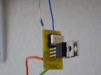
I decided to use the AVAGO photovoltaic coupler type no ASSR-V621 (from Farnell) and the IRF2907 FET which offers a "typical" Rds of around 3.5mΩ. This figure is quoted with 10 volts across gate and source. As each relay would use one ASSR-V621 i decided to connect both photovoltaic cells in series to maximise the available drive voltage.
Test were done as follows.
LED's in coupler were run at 12ma and 7ma to test. Open circuit voltage was 15.26 and 14.72 volts respectively.
Next a 1MΩ load was applied and the test repeated. Voltages this time were 13.93 and 10.66 volts.
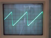
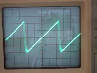
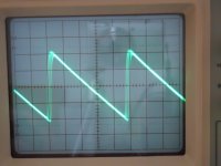
Some real world tests were done using an old Rotel RA820 amplifier with the SS relay in series with a 5 ohm resistor. Shots below show the result. What you are looking at is both traces on a dual trace 'scope overlaid. In other words the voltage at each side of the relay. There is no visible loss or deviation before and after the relay. The test was done at 10khz repetition rate at 40 volts peak to peak swing and then at 200 millivolts peak to peak swing. The "distortion" on the positive and negative going slopes on the 200mv shots is due to low level hum from the generator/leads/physical position of generator on top of amp making its presence felt.
All in all a good result I feel. There was no noticeable heating of the FET's even at 40 volts into 5 ohms... maybe not stone cold but definitely not even warm.
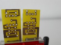
The PCB's I made in two flavours as (shame on you Mooly) until I delve into the "Mooly" amp I can't remember what the polarity is of the relay coil connections on the PCB's (it was all pre PC and done on paper... as you do/did) and the hand produced board layouts are long gone.
This little exercise also shows how good Diptrace is at producing excellent PCB's using a cheap Inkjet printer and transparency/UV light box. The IC interconnections are 0.3mm. The dark bits on the PCB are just a bit of ink.
I decided to use the AVAGO photovoltaic coupler type no ASSR-V621 (from Farnell) and the IRF2907 FET which offers a "typical" Rds of around 3.5mΩ. This figure is quoted with 10 volts across gate and source. As each relay would use one ASSR-V621 i decided to connect both photovoltaic cells in series to maximise the available drive voltage.
Test were done as follows.
LED's in coupler were run at 12ma and 7ma to test. Open circuit voltage was 15.26 and 14.72 volts respectively.
Next a 1MΩ load was applied and the test repeated. Voltages this time were 13.93 and 10.66 volts.
Some real world tests were done using an old Rotel RA820 amplifier with the SS relay in series with a 5 ohm resistor. Shots below show the result. What you are looking at is both traces on a dual trace 'scope overlaid. In other words the voltage at each side of the relay. There is no visible loss or deviation before and after the relay. The test was done at 10khz repetition rate at 40 volts peak to peak swing and then at 200 millivolts peak to peak swing. The "distortion" on the positive and negative going slopes on the 200mv shots is due to low level hum from the generator/leads/physical position of generator on top of amp making its presence felt.
All in all a good result I feel. There was no noticeable heating of the FET's even at 40 volts into 5 ohms... maybe not stone cold but definitely not even warm.
The PCB's I made in two flavours as (shame on you Mooly) until I delve into the "Mooly" amp I can't remember what the polarity is of the relay coil connections on the PCB's (it was all pre PC and done on paper... as you do/did) and the hand produced board layouts are long gone.
This little exercise also shows how good Diptrace is at producing excellent PCB's using a cheap Inkjet printer and transparency/UV light box. The IC interconnections are 0.3mm. The dark bits on the PCB are just a bit of ink.
Attachments
-
 10Khz 40 Volts Pk Pk (2) (1024x768).jpg387.9 KB · Views: 1,875
 -
 10Khz 40 Volts Pk Pk (1024x768).jpg416.3 KB · Views: 1,738
 -
 10Khz 200 Millivolts Pk Pk (1024x768).jpg416.9 KB · Views: 1,670
 -
 10Khz 200 Millivolts Pk Pk (2) (1024x768).jpg415.6 KB · Views: 1,677
 -
 Two Flavours Of PCB (1024x768).jpg367.6 KB · Views: 1,625
 -
 Prototype (1024x768).jpg327.5 KB · Views: 915
- Home
- Amplifiers
- Solid State
- Output Relays