Is it worth checking SOA at turn ON when using these as supply rail relays?
0.3ms is a significant proportion of 1ms SOA at turn on.
The OFF seems to be adequately fast, ~40us delay and then a switching period <<10us.
If used as supply rail switches and particularly if there is a significant rail capacitance to charge then yes, I suppose SOA could be compromised depending on the device chosen.
I wonder if it might make sense to wire the AVAGO outputs in parallel to reduce switching times, the data sheet for the PVI5013 says "The dual-channel configuration allows its outputs to drive independent discrete power MOSFETs, or be connected in parallel or in series to provide higher-current drive for power MOSFETs or higher-voltage drive for IGBTs." It could be a better way to go.
Mike
Hi Mike,
The AVAGO data sheet I have for the ASSR-621 does say that the cells can be connected in series. I think for a speaker relay there is no issue at all with both on and off times.
I went for series connection to maximise gate drive voltage to ensure lowest possible Rds of the FET's
I wonder if it might make sense to wire the AVAGO outputs in parallel to reduce switching times, the data sheet for the PVI5013 says "The dual-channel configuration allows its outputs to drive independent discrete power MOSFETs, or be connected in parallel or in series to provide higher-current drive for power MOSFETs or higher-voltage drive for IGBTs." It could be a better way to go.
Mike
Yes, this what I will do.
Good luck!
Please do, I am 50yo and have been driving amplifiers for 30, started with a 25W Akai and slowly worked my way up to the 120Watter I use now. I have never had a problem with any of my amps until today, when it did trip successfully & shut itself down - awesome. I rebooted her and away she went. Good as gold.
I remember when I bought my first motorbike, it was a fuel injected 1000cc job. The dealer told me to take it out and give it a good flogging to run it in. I felt insulted by what he had said, firstly; because he put my life in danger, and secondly; because my Dad told me to take it easy for a while and change the oil frequently. I told the dealer he was wreckless and that his attitude stunk, to which he replied "Listen mate, you don't have a dog and bark yourself".
Running a powerful amp is an exercise in self control, but as human beans we are flawed, and when we think no-one is listening, we sneak into the lounge, crank up the stereo, pick up the nearest stick and play air guitar. Now dont you?
Getting back to the dog analogy; I think we have to be honest about why we like big amplifiers & contrary to what the psychologist will tell you, I believe it has nothing to do with compensating for an inferior anatomy.
I reckon that I have a big stereo because I like to play loud Acoustic-Blues music, and if I am to be completely honest I must admit that I want other people to listen to my music too.
Sorry I'm drifting off the subject a bit; So I will make my point in one sentence:
If you have bought or even built a big amp, then you are going to test it out. It's better to have all the protection you can get because as builders we know how heart-breaking this kind of failure is - not to mention the shame.
I would like to encourage you to continue with your project and personally wish you all the best. You may be on the cusp of something big - who knows!
I really like your philosophy on the virtual implementations of amplifier circuits.
Good luck - Phil Elliott
As I mentioned, if I have the inclination I might do a real test.....
Please do, I am 50yo and have been driving amplifiers for 30, started with a 25W Akai and slowly worked my way up to the 120Watter I use now. I have never had a problem with any of my amps until today, when it did trip successfully & shut itself down - awesome. I rebooted her and away she went. Good as gold.
I remember when I bought my first motorbike, it was a fuel injected 1000cc job. The dealer told me to take it out and give it a good flogging to run it in. I felt insulted by what he had said, firstly; because he put my life in danger, and secondly; because my Dad told me to take it easy for a while and change the oil frequently. I told the dealer he was wreckless and that his attitude stunk, to which he replied "Listen mate, you don't have a dog and bark yourself".
Running a powerful amp is an exercise in self control, but as human beans we are flawed, and when we think no-one is listening, we sneak into the lounge, crank up the stereo, pick up the nearest stick and play air guitar. Now dont you?
Getting back to the dog analogy; I think we have to be honest about why we like big amplifiers & contrary to what the psychologist will tell you, I believe it has nothing to do with compensating for an inferior anatomy.
I reckon that I have a big stereo because I like to play loud Acoustic-Blues music, and if I am to be completely honest I must admit that I want other people to listen to my music too.
Sorry I'm drifting off the subject a bit; So I will make my point in one sentence:
If you have bought or even built a big amp, then you are going to test it out. It's better to have all the protection you can get because as builders we know how heart-breaking this kind of failure is - not to mention the shame.
I would like to encourage you to continue with your project and personally wish you all the best. You may be on the cusp of something big - who knows!
I really like your philosophy on the virtual implementations of amplifier circuits.
Good luck - Phil Elliott
Hi farmerjack61,
Thanks for the kind words but it's hardly "my project"... I can't take any credit for the idea of using photovoltaic couplers.
In fact for me this guy got the ball rolling, and I had always intended to come back and look at the idea further.
http://www.diyaudio.com/forums/solid-state/155939-mosfet-relais.html
And then Michael Bean mentioned the couplers... and the rest is history.
(The testing was the results I posted earlier today on the on/off behavior 🙂)
Member
Joined 2009
Paid Member
For a new amp design where the SS relay might as well go into the gnd return from the speaker - how would you implement this ?
If it disturbs you it's wrong until either the machine or your mind is changed." Robert M Pirsig.
Hi there Bigun, I know we haven't met before but I just wanted to say that I agree with Pirsig, It's a matter of how much satisfaction you can extract from your hobby. My new amp makes a bit of noise but if I look away from the speakers in-between tracks and concentrate on the nice plump sound during the recording - all the hum just blends into the background!
We love our 'home-brew' amps - Just like a mother loves her baby - It's all a matter of perspective.
PS Are you named Bigun because you're a largish man or because you have a Big Gun, or perhaps both? The latter would be handy whilst wrestling angry Moose up there in the frosty places.
Cheers and bye for now. Farmerjack
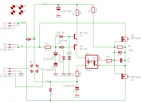
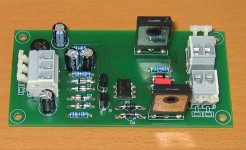
This is the schematics that I have developed. It works well, without problems. It is supplied from center tapped secondary of the main transformer, in my case it is 2 x 42Vrms, but would work both with lower or higher voltage. I can post photos and PCB, if someone is interested.
Attachments

Very nice Pavel.
So you are using the opto to turn off the FET's. I'll have to think about this one 🙂
Does it allow max voltage swing from the amp to be passed OK (gate source voltage maintained as output rise)... it's a bit early in the morning here...
Nice one 🙂
So you are using the opto to turn off the FET's. I'll have to think about this one 🙂
Does it allow max voltage swing from the amp to be passed OK (gate source voltage maintained as output rise)... it's a bit early in the morning here...
Nice one 🙂
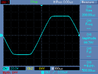
Thanks... that looks good. 0.5 volt is nothing in the scheme of things
It would be interesting to see your measurements as I think the FET approach has a lot going for it.
It would be interesting to see your measurements as I think the FET approach has a lot going for it.
Member
Joined 2009
Paid Member
PS Are you named Bigun because you're a largish man or because you have a Big Gun, or perhaps both? The latter would be handy whilst wrestling angry Moose up there in the frosty places.
...well it's a nickname I picked up from a friend many years ago who just happened to have the exact same nickname - all happened when I used to live in London (before I emigrated) - not sure of the origin but it ain't the Moose you have to worry about up here, it's the bears... 😱
This is the schematics that I have developed. It works well, without problems. It is supplied from center tapped secondary of the main transformer, in my case it is 2 x 42Vrms, but would work both with lower or higher voltage. I can post photos and PCB, if someone is interested.
wow, thanks for sharing this. I'd prefer to use a proven circuit than invent my own when it comes to speaker protection. However, I need a single pcb that will protect 3 channels (HT amp) and I have a couple of UPC1237H chips on order - so my plan is to use this chip to driver 3 SS relays. However, perhaps your circuit is better - not sure I understand the benefits of your schematic.
Yes, thanks Pavel, a very neat job.
Do you feel FET switching is a way forward or would you still prefer a relay given a choice ? Personally I prefer the FET based on my experiences.
D7 ? I'm guessing your running the FET's at least with around 10 or 12 volts Vgs for minimum on resistance. When I was looking for FET's I picked the IRF2907 because of its very low Rds (and I could get them locally 🙂) and run these at around 16 volts Vgs although the 2907 is less well specced for current and volts although fine for lower powered amp.
Any benefit in two pairs in parallel do you think ?
I have evaluated this MOSFET relay circuit for several months in a real 2 x 250W amplifier and there has been no problem. I have also evaluated faulty conditions with switching off the load. The schematics posted is complete. The part is IRFP90N20D. The circuit is very rugged and capable to interrupt higher DC currents than a 10 - 30A relay.
However, I still use a 30A, double contact relay in my power amplifiers for sale. The main reason is that the MOSFET relay does not turn off instantly after power shut down (power switch off). It continues to conduct current, though with higher resistance, until the gate charge is not discharged into gate-source resistor. Anyway, under faulty conditions (DC at the output) it works perfect and saves speakers by disconnecting them in a more reliable way than the standard relay.
However, I still use a 30A, double contact relay in my power amplifiers for sale. The main reason is that the MOSFET relay does not turn off instantly after power shut down (power switch off). It continues to conduct current, though with higher resistance, until the gate charge is not discharged into gate-source resistor. Anyway, under faulty conditions (DC at the output) it works perfect and saves speakers by disconnecting them in a more reliable way than the standard relay.
Interesting to hear you have tested the interrupt capability. I'm convinced this is the way for new designs in doing away with the mechanical contacts of a relay. The protection aspect has to be better than contacts that could weld.
A very elegant design.
A very elegant design.
Might it be possible to have a second means, another opto-coupler even, to turn off the MOSFETs whilst the rails still maintain some potential. It could be actuated when say, the AC supply is disconnected.I still use a 30A, double contact relay in my power amplifiers for sale. The main reason is that the MOSFET relay does not turn off instantly after power shut down (power switch off). It continues to conduct current, though with higher resistance, until the gate charge is not discharged into gate-source resistor... .
Very nice circuit PMA - simple and elegant.
I am working very hard on my new amp and hope to be able to post it up in a month or so. For speaker protection I have used mosfet SSR also, but mine is combined with an MCU because I am doing speaker muting, over-temp, in-rush current limiting etc. I have used Fairchild 150V 4mO devices (but they are on back order, so I used some 20mO parts in the interim for testing). I have decided I will definitely not go back to relays in the future.
I am working very hard on my new amp and hope to be able to post it up in a month or so. For speaker protection I have used mosfet SSR also, but mine is combined with an MCU because I am doing speaker muting, over-temp, in-rush current limiting etc. I have used Fairchild 150V 4mO devices (but they are on back order, so I used some 20mO parts in the interim for testing). I have decided I will definitely not go back to relays in the future.
This is the schematics that I have developed. It works well, without problems. It is supplied from center tapped secondary of the main transformer, in my case it is 2 x 42Vrms, but would work both with lower or higher voltage. I can post photos and PCB, if someone is interested.
Patel,
Forgive my ignorance, does the scheme include DC detection? thanks
Ken
- Home
- Amplifiers
- Solid State
- Output Relays