Hello Jan,
Nothing fishy or magic here. It is all in the details of the QA401 software code.
As in Le := (calculation results) Le is only a variable name; in this case on the Z (impedance) scale. Le is labeled in H units if the current lags voltage and labeled in f units if the voltage lags current. I assume that an If,Then statement is used in the software code. E L I, I C E
For this test setup the voltage across a 0.01Ohm current sense resistor is user to calculate the test circuit current; E/R = I. Knowing the test circuit current the voltage across the DUT is user to calculate the DUT impedance; E/I = R.
For more information:
First log in at ap.com
Measuring Loudspeaker Impedance Using APx Derived Measurement Results - Audio Precision
Mark,
I remember that there are several impedance models for speaker impedance including off the top of my head “Wright”.
I doubt that the QA401 software uses a simple resistance in parallel with a capacitance to calculate their plots.
Here is a model, not the "Wright" model. pun
Activity: Measuring a Loudspeaker Impedance Profile [Analog Devices Wiki]
Thanks DT
Nothing fishy or magic here. It is all in the details of the QA401 software code.
As in Le := (calculation results) Le is only a variable name; in this case on the Z (impedance) scale. Le is labeled in H units if the current lags voltage and labeled in f units if the voltage lags current. I assume that an If,Then statement is used in the software code. E L I, I C E
For this test setup the voltage across a 0.01Ohm current sense resistor is user to calculate the test circuit current; E/R = I. Knowing the test circuit current the voltage across the DUT is user to calculate the DUT impedance; E/I = R.
For more information:
First log in at ap.com
Measuring Loudspeaker Impedance Using APx Derived Measurement Results - Audio Precision
Mark,
I remember that there are several impedance models for speaker impedance including off the top of my head “Wright”.
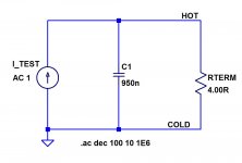
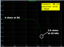
I doubt that the QA401 software uses a simple resistance in parallel with a capacitance to calculate their plots.
Here is a model, not the "Wright" model. pun
Activity: Measuring a Loudspeaker Impedance Profile [Analog Devices Wiki]
Thanks DT
Last edited:
Hello Jan,
Nothing fishy or magic here. It is all in the details of the QA401 software code.
As in Le := (calculation results) Le is only a variable name; in this case on the Z (impedance) scale. Le is labeled in H units if the current lags voltage and labeled in f units if the voltage lags current.
OK, yes I can follow that logic. It's just that Le is normally understood as L(equivalent) in Henries.
What will they think of next?

Jan
Hi Pete,Hi Ian,
Any chance you could send me or post those other versions? I want to see if
he gives anymore clues about the Self power amp.
I found the #55 cable was 37*0.32mm inner. This was listed in the cable models of the last known version 12 April 2008 on page 14. It is attached.
Also attached is a zip with MC7 files that Cyril sent me.
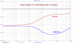
One of these files, Cap3.tif, shows the feedback in dB with frequency for both amps for signal reaching the input stage. I'm not sure where the signal was injected for this plot. I presumably includes the output inductor and Zobel. There is a test in Part 2* p26 "Zobel RF attenuation" where the signal was injected with an unterminated cable present -- but not sure if a cable was present for the plot . (*Part 2 link Re: Cyril Bateman Capacitor Sound Archive - Pro Audio Design Forum)
What I find strange is that both amps oscillated with his unterminated #55 cable. It therefore cannot be attributed simply to Self feedback capacitor across the feedback resistor - it would be an easy problem to solve if it was due to that capacitor. Of course you could solve the problem by not using any exotic speaker cables, but that's too easy
.Attachments
Hello,
Coming in the mail is a copy of Bob’s hard cover book.
Starting from the premise that we want to see how different amplifiers misbehave with different loads. I am thinking that some loads are more difficult to drive than others. Included in the difficult to drive concept can be multiple culprits; inductance, capacitance, variable impedance, variable phase and reflections (aka resonance peaks) to feed back to the amplifier. Oscillation and positive feedback kills amplifiers.
Like it or not, the cables are part of the driven load. Operating your Blameless amplifier with only the fancy capacitive cables attached is an invitation to oscillation.
Looking at the attached reports (post #9905) it looks like the lossy PVC insulated zip cord performed the best, with the least distortion. Seems to me that a real connected load with resistance that turns amps and volts into watts and heat outside of the amplifier will damp the transmission line reflections that kill amplifiers.
This upcoming weekend, Thursday, Friday, Saturday and Sunday, I will have time in the lab. The plan is to test 12AWG zip cord from allelectronics.com, 12AWG PVC insulated THHN off the roll and 12 AWG silver plated Teflon insulated cable from apexjr.com. Also to be tested are two 4ohm mills 12watt resistors for a baseline, a 12 inch JBL2204H and a cheap 12 inch buyout special from partsexpress.com both drivers in a 2 ft^3 sealed box. I have a couple of parasound amplifiers to test. I am not using the apx1701 first. The parasound zamp v.3 is first.
What do you think? A apx555 THD+N, SINAD, multitone and FFT out to 1M to see reflections?
Thanks DT
I'm going to buy the second edition of Bob's book, has anyone found it on sale for less
than the Amazon price of $83? I'll check to see if it drops tomorrow.
It is on Amazon now for $62.98, much lower than the dip on Black Friday so I bought it.
There are a few left.
Hi DualTriode,
If you want to live dangerously then why not make one of Cyril's exotic cables #44 and #55 both 5 metres?
From Cyril's tests we know Bi-polar amps can blow up with them and lateral amps can survive. So using a lateral amp would be safest.
Also on p19 of Pt 1+2 Cyril wrote:
"With unterminated 10metre lengths, all cables including the 79 Strand resulted in RF oscillations with one or both amplifiers and one or more test loads. Oscillation frequencies now ranged from a low of 1.85MHz for the 10metre #55 cable to a high of 3.8MHz for the 10metre 79 Strand cable."
His 79 strand 5m cable did not oscillate with no termination. So it depends on cable length.
"... Simulations then confirmed these reflections could result with all my cables with lengths up to 20metres. However much smaller and usually out of phase reflections were found using 100R cables longer than 20metres."
Cyril also found that it depends on inductance in the output stage resistors. He measured the Self amp 0.22R emitter resistors at 0.3mH inductance. When he replaced them with low inductance resistors the amp blew up (I assume cables were attached). In hindsight Cyril should have changed the compensation after changing to low inductance resistors.
Re tests to detect or provoke oscillation with cables:
I have no experience doing this. I assume some members are now working on it and will share details. Cyril's method of monitoring oscillation was a high impedance scope probe on the input stage inverting input with a 1kHz sinewave stepped in level for 1V to 5V output for the problem cables and full output if there was no oscillation.
Related is simulations showing oscillation with cables like Cyril used (or whatever):
If someone can do this then we have a good chance of understanding what causes it and how best to prevent it even with unterminated cables and with exotic cables.
BTW Cyril's sim circuit for the Self and Maplin amp Zobel and output inductors can be found in 'Cap2.tif' in the zip file above (post 9905). IIRC Cyril also simulated the Maplin amp in one of his articles (not sure which). Anyone?
Hi Pete,
What I find strange is that both amps oscillated with his unterminated #55 cable. It therefore cannot be attributed simply to Self feedback capacitor across the feedback resistor - it would be an easy problem to solve if it was due to that capacitor. Of course you could solve the problem by not using any exotic speaker cables, but that's too easy
Possibly the leads could act as an aerial at some critical tuned frequency. The lead capacitor impedance reduces with increasing frequency whereas the feedback transistor base emitter junction diode could be a detector.
In the Super Gain Clone thread there is a 22k stopper resistor in series with the 47p lead capacitor making this a step network in parallel with the 20k feedback resistor.
I came up with a lumped approximation to the #55 plus speaker load and took a guess
at the 50W Blameless amp for simulation as shown in this thread:
https://www.diyaudio.com/forums/sol...r-speaker-cable-interactions.html#post6003251
It did not oscillate with the test load but I seem to recall one of our members (jcx?) saying
that certain simulator settings should be used when looking for oscillations - I don't recall
what those were.
Not having more info about Cyril's amps makes it difficult to refine the simulation.
I suppose a TIAN probe should be added so that the margins with resistive loads can be
compared to the cable-speaker load.
Last edited:
Looking at some old images for Self's original design I did not see any step network in parallel with the feedback resistor.
Self's Cdom value was identical to that in the .asc you posted. The pole associated with Self's version would have been ten times lower than any natural pole existing in his circuit.
I am assuming the version you posted is due to Bateman.
If this was subject to stability problems it is due to the modifications he made to Self's circuit giving rise to a conflict in poles - such there is less than 10 times dominance of one anywhere in the circuit.
I ran the simulation posted with the nfb divider arm to earth was disconnected - a rough check on unity gain. The simulation took an age to run and the result suggested Bateman's circuit is not unity gain stable.
It would be as well to run a TIAN probe to see what to do about this.
It's right there in the LM3886 datasheet, and I suspect that was Bob's inspiration for installing it in the original Super Gain Clone.In the Super Gain Clone thread there is a 22k stopper resistor in series with the 47p lead capacitor making this a step network in parallel with the 20k feedback resistor.
Attachments
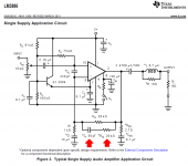
It's right there in the LM3886 datasheet, and I suspect that was Bob's inspiration for installing it in the original Super Gain Clone.
Thanks Mark. I enjoyed looking through the datasheet. Do you know who designed the LM3886? Y/N.
... He measured the Self amp 0.22R emitter resistors at 0.3mH inductance....
0.3mH seems unlikely. That's a big coil. It could be a crossover choke. Yet we know small resistors don't do that. It suggests a corner at 100Hz, and large droop above 5kHz.
Maybe uH? Then the droop is a more reasonable 5MHz, a point that hot tranny amps can get in trouble.
Oops
Hi PRR,
Oops -- 0.3uH or 300nH. Measured at 10MHz 19 ohms. Sorry.
0.3mH seems unlikely. That's a big coil. It could be a crossover choke. Yet we know small resistors don't do that. It suggests a corner at 100Hz, and large droop above 5kHz.
Maybe uH? Then the droop is a more reasonable 5MHz, a point that hot tranny amps can get in trouble.
Hi PRR,
Oops -- 0.3uH or 300nH. Measured at 10MHz 19 ohms. Sorry.
Bob,
Question regarding IPS degeneration, IPS current, and Cmiller. A common configuration seems to be Re=100 Ω, Cm=100 pF and I=1-4 mA. It's obvious that increasing Re allows for reducing Cm and it would seem that a higher current would also increase the slew rate, but both are at the expense of some increase in noise. I've seen Re as high as 470 Ω with Cm as low as 30 pF in some designs. That would include your figure 3.14, the high power version of the design evolution, (and figure 9.2, though IPS current is reduced to 1 mA). Why the change to that particular version after using 220 Ω and 62 pF in the versions just before it? Then, figure 4.1 shows 220 Ω and 27 pF.
What are the tradeoffs and how high could one reasonably go with Re to minimize the size of Cm? What is the optimum configuration, or is optimum really over a range of values? Also, is there any reason to change the degeneration resistor values in the current mirror?
Thanks.
Fred, one purpose of using emitter degeneration resistors in a current mirror, is to elevate the output impedance of the mirror. In my own personal opinion, you want the current mirror output impedance to be at least 3X greater than the input impedance of the second stage (called VAS), in order to maximize gain. That means 500K to 1M ohm output impedance, for the type of EF-CE VAS often seen in Bob's book.
Another purpose of using emitter degeneration in a mirror, is to negate the impact of mismatched transistors. If the delta-VBE between the two transistors is X millivolts, then you can select degeneration resistor values such that N*X millivolts are dropped across the resistors. This reduces the impact of delta-VBE by a factor of N. I myself tend to assume X=5 millivolts of delta-VBE, and I tend to choose N=50x. Thus I drop 250mV across the emitter resistors, generally.
250 mV is a friendly number and easy to remember because: you're dropping about 10X more millivolts across the external emitter resistor, than you're dropping across the internal emitter resistor "re" . From the hybrid pi model, re = 1/gm = (Kt/q / IC) . Thus the voltage dropped across re is (kT/q) = 25 millivolts at room temperature. Multiply by ten and you get: 250 mV across the external emitter resistor. Easy!
Emitter Degen is also important to linearize the LTP pair and it ensures you avoid SID. Without Degen, you only need a small differential between the two inputs - even with feedback - to drive the diff pair into its non-linear operating region.
I tend to use a model and then examine the linear operating region - IIRC on the two VFA's I did, the linear operating region was about 500mV for the one amp, and ~1volt for the other.
I tend to use a model and then examine the linear operating region - IIRC on the two VFA's I did, the linear operating region was about 500mV for the one amp, and ~1volt for the other.
- Home
- Amplifiers
- Solid State
- Bob Cordell's Power amplifier book