> swap the battery with the other one in the charger. Pure DC. Now, what about your "special" line cord?
The battery will remember if it was charged from a $3 cord or a $3,000 cord. 😀
The battery will remember if it was charged from a $3 cord or a $3,000 cord. 😀
Slightly off-topic. Has anyone used a toroid power transformer with the usual 2-winding primary as a line isolation transformer by connecting one primary to the line and the other primary to the load?
In such a case, I'm guessing that its capability would be on the order of half its normal rated VA, since only half of the usual primary is being used for line input, assuming that copper losses are the governing constraint.
In a similar context, might a conventional non-toroid transformer with dual primary windings provide a bit more isolation? Most times I've measured primary-secondary capacitance, the toroid of similar VA has had more capacitance, but I have never measured capacitance between the two primaries of either type of transformer.
Thoughts?
Cheers,
Bob
I have used 2 identical transformers for isolation by connecting all secondaries of the first transformer to the second, then taking the output from the primary of the second transformer.
Most isolation transformers will have very high voltage breakdown between primary and secondary. If this is needed in ones application, the the bifilar, or even dual primary, may not be good. The 2 transformer solution does help, though we are probably still short of 5 kV breakdown.
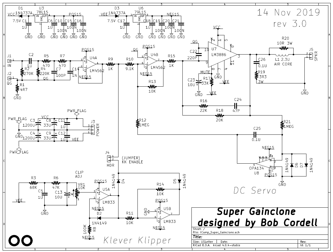
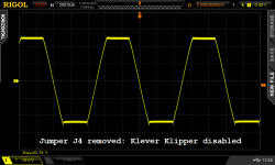
Bob's Klever Klipper in action
I've now got a step-by-step procedure for adjusting the Klever Klipper. It appears to me that when you get the KK dialled in correctly, it works very, very well.
Here are the before-and-after photos of the same amp ("Super Gain Clone") with the same 1 kHz input sinewave driving both channels, and the same load resistors. We drive both channels to get the max possible "sag" on the power supply, so the amp will clip even sooner. The only thing that changed between the two pictures is the installation / removal of jumper wire J4, which enables / disables the KK.
It sure does look awfully nice to me.
_
Attachments
I have used 2 identical transformers for isolation by connecting all secondaries of the first transformer to the second, then taking the output from the primary of the second transformer.
Most isolation transformers will have very high voltage breakdown between primary and secondary. If this is needed in ones application, the the bifilar, or even dual primary, may not be good. The 2 transformer solution does help, though we are probably still short of 5 kV breakdown.
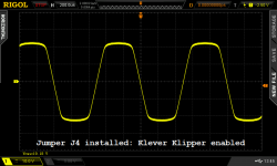
Attached is a shot of a toroidal transformer from my "black museum" which I replaced.
After one of the primary winding ends had broken off I unwound the secondary to see if I could get good enough access to repair the broken end.
The primary insulating tape can be seen. As to the number of layers one would be guessing as to how many would be enough.
The transformer was a 25V-CT-025V ac of 160VA. I would expect the insulation for a mains isolation transformer would need to be more substantial.
With no insulation between a primary and a secondary winding this idea should be laid to rest.
Attachments
Hi Pete,Does anyone know what Cyril's #55 cable was, brand and model?
I searched my archives and found two other version of Cyril's article with extra on these:
"I had available three 4.9 metre long development cables having nominal RF impedances of 30R, 16R and 14R. I selected the 14R impedance, my highest capacitance cable, labelled as #55 made using Raychem 55A0111 wire. With 440pF/metre, it has slightly more than double the Supra 2.0 capacitance, perhaps that might produce a measurable distortion difference. This 440pF/metre presents a very modest capacitance compared to some commercially available cables which have more than 1500pF/metre."
"The 79 strand and Supra cable descriptions are inexpensive commercial types. Both cables are "balanced" twin lines, one a 79 strand zipwire construction, the other is two rectangular parallel multistrand wires. The remaining three were all handmade co-axial types, identified by the wire used for the inner wire and its insulation. All three outer screens were made using the same double braidwire screens and each coaxial inner wire was chosen to have near identical cross-section and DC resistance. ... The DCR for the PTFE was 0.0511R, #44 was 0.0538R and #55 was 0.0548R"
A search on Raychem 55A0111 turned up various gauge, eg 16AWG 55A0111-16 | 16 AWG Raychem Spec 55 Aerospace Cable and insulation is XL-ETFE 0.006" thick. Presumably the "#55" is the Tyco Raychem spec 55 (since another Tyco Raychem spec is 44). The actual gauge Cyril used can be calculated from the DCR for 5m (homework).
IIRC Cyril said it was not easy to pull the 5m braid screens through and the inner wire.
Last edited:
Hello Mark.It sure does look awfully nice to me.....
What distortion profiles and distortion measurements do you get in the two overload cases ?.
How do the overload sounds compare subjectively ?.
Dan.
Last edited:
That was my last gasp of DIY for quite a while now. We're repairing / renovating four rooms of the house and everything's going into storage so the demolition crew can begin. Will soon know whether "PODS" storage bays are a good or terrible idea.
I feel your pain mark, I’ve been building our house for over 3 yrs now, been living in it unfinished for just over a yr now since hurricane Michael wiped out our camper, it recently came down to where I have to finish the loft area that I had my interim entertainment center set up........all the goodies are boxed up awaiting their new home in the living room.
Gonna be a couple months......having withdrawal symptoms and not being able to move fwd with testing is aggravating to say the least, but it will pass!
Edit.....my experience with pods is they leak in the corners so be careful to keep stuff off the floor.
Gonna be a couple months......having withdrawal symptoms and not being able to move fwd with testing is aggravating to say the least, but it will pass!
Edit.....my experience with pods is they leak in the corners so be careful to keep stuff off the floor.
Hi,
Off topic i know - but why don't the US build their houses out of bricks ?
I see on the TV many problems of fires burning houses down, and hurricane demolishing wooden houses. Is there a brick embargo on, in the US ?
Regards,
Shadders.
Off topic i know - but why don't the US build their houses out of bricks ?
I see on the TV many problems of fires burning houses down, and hurricane demolishing wooden houses. Is there a brick embargo on, in the US ?
Regards,
Shadders.
Hi Pete,
I searched my archives and found two other version of Cyril's article with extra on these:
"I had available three 4.9 metre long development cables having nominal RF impedances of 30R, 16R and 14R. I selected the 14R impedance, my highest capacitance cable, labelled as #55 made using Raychem 55A0111 wire. With 440pF/metre, it has slightly more than double the Supra 2.0 capacitance, perhaps that might produce a measurable distortion difference. This 440pF/metre presents a very modest capacitance compared to some commercially available cables which have more than 1500pF/metre."
"The 79 strand and Supra cable descriptions are inexpensive commercial types. Both cables are "balanced" twin lines, one a 79 strand zipwire construction, the other is two rectangular parallel multistrand wires. The remaining three were all handmade co-axial types, identified by the wire used for the inner wire and its insulation. All three outer screens were made using the same double braidwire screens and each coaxial inner wire was chosen to have near identical cross-section and DC resistance. ... The DCR for the PTFE was 0.0511R, #44 was 0.0538R and #55 was 0.0548R"
A search on Raychem 55A0111 turned up various gauge, eg 16AWG 55A0111-16 | 16 AWG Raychem Spec 55 Aerospace Cable and insulation is XL-ETFE 0.006" thick. Presumably the "#55" is the Tyco Raychem spec 55 (since another Tyco Raychem spec is 44). The actual gauge Cyril used can be calculated from the DCR for 5m (homework).
IIRC Cyril said it was not easy to pull the 5m braid screens through and the inner wire.
Hi Ian,
Any chance you could send me or post those other versions? I want to see if
he gives anymore clues about the Self power amp.
It's a money reason. Bricks are one of most expensive house exteriors to buy & install, ask a Mason for a quote to brick your house.but why don't the US build their houses out of bricks ?
Or put it the other way: Thanks to a superabundance of supply, and happy proximity to heavily forested and logged Canada, the (western) US has unusually low priced wood.
In my little neighborhood (150 mile radius from San Francisco), the devastation of the Great Earthquake of 1906 has made people leery of stone/brick buildings. Wood, reinforced concrete, steel are favored instead. These preferences were reinforced after the 2014 South Napa earthquake, when the buildings that suffered greatest damage (e.g. Napa County Courthouse) were made of stone. Same for the 1989 Loma Prieta quake: the banks in downtown Santa Cruz that fell down, were made of brick.
In my little neighborhood (150 mile radius from San Francisco), the devastation of the Great Earthquake of 1906 has made people leery of stone/brick buildings. Wood, reinforced concrete, steel are favored instead. These preferences were reinforced after the 2014 South Napa earthquake, when the buildings that suffered greatest damage (e.g. Napa County Courthouse) were made of stone. Same for the 1989 Loma Prieta quake: the banks in downtown Santa Cruz that fell down, were made of brick.
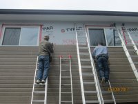
The cheapest house exterior siding these days is vinyl by a long shot. 2 years ago we sided the garage/loft, 768 sq. ft. I do not like vinyl, I chose CanExel® Ridgewood D-5, basically pre-finished imitation wood siding, I get comments on how good it looks, you tell me. Nothing like hopping across ladders, to save time going up and down 🙂 I found out what Bursitis in the hip is all about after that job was done.
Attachments
Last edited:
Hi,
I can see how for earthquakes that wood is a better material. I suppose the cost of rebuilding wooden homes multiple times is cheaper than a brick built house that would need some repair.
Regards,
Shadders.
I can see how for earthquakes that wood is a better material. I suppose the cost of rebuilding wooden homes multiple times is cheaper than a brick built house that would need some repair.
Regards,
Shadders.
Hi,
Off topic i know - but why don't the US build their houses out of bricks ?
I see on the TV many problems of fires burning houses down, and hurricane demolishing wooden houses. Is there a brick embargo on, in the US ?
Regards,
Shadders.
Walt's attempt to educate: YouTube
... I suppose the cost of rebuilding wooden homes multiple times is cheaper....
Wood houses don't get rebuilt "multiple times". Most don't burn or blow down for 50-100 years. Far more get modified or demolished because the ever-moving population wants something different.
America can be COLD (or hot). In most of the US we use 5.5" insulation in walls. I'm told modern UK houses have insulation between the withes but nobody says how much. Assuming standard brick, 5.5" insulation makes a quite thick wall, 13"? Windows look funny. (Though I do know a building with 18" walls, it is a school, and still the windows look funny.) Chipboard on studs is 7" thick.
And as said, we have ample trees in the US NW and Canada, both coasts (my lumber comes from Quebec to Nova Scotia). Lots of trees in Maine but harvesting them is down to labor politics. At present most of Maine is "reserve", long term investment.
Last edited:
Hi Ian,
Any chance you could send me or post those other versions? I want to see if
he gives anymore clues about the Self power amp.
For what it is worth Silicon Chip magazine from Australia has published power amplifier circuits largely based on the the original Blameless. In the mid 1970's for the output stability part of circuits one proposed by A.N.Thiele started to appear.
An example from the most recent article in Silicon Chip - January 2017 is an output coil of 2.2uH in parallel with 6.8R with the speaker output end connected to 0V earth by a 100n capacitor.
The description given is the coil isolates any added capacitance ( e.g. from cable or the crossover network) from the amplifier at high frequencies which could otherwise cause oscillation. The resistor reduces the inductor's Q to damp ringing and also forms a Zobel network with the 100 nF capacitor which also aids stability.
In the past claims have been made this type system makes an amplifier unconditionally stable. It might need development with the component values to cope with the licence that could be used with devising development speaker cable.
In my book it should be the job of the speaker cable manufacturers to design their cable to suit a range of amplifiers. Self was designing amplifiers in the same ear as Cyril Bateman so if nothing good eventuated out of the development tests in the end he may have abandoned this exercise accordingly.
I remember a time when amplifiers were slated because some bright speaker designer had come up with a complex crossover that made for a load too difficult to drive.
A lot of these were liked by the reviewers who should have regarded this as a reason not to buy the particular product.
Hi Pete, check your PMHi Ian,
Any chance you could send me or post those other versions? I want to see if
he gives anymore clues about the Self power amp.
capacitance hiding somewhere
Hello,
This is beginning to perk my interest.
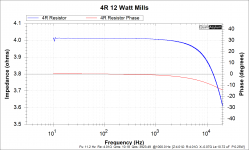
There is a QA401 Audio Analyzer sitting here test driving the speaker impedance application. The amplifier will be called nameless. To setup the baseline there is a 12Watt 4Ohm Mills resistor, the kind used in a quality crossover. The connecting speaker wires are 5 feet long fine stranded 12 AWG flexible silicone rubber insulated, the kind used for test instrument leads.
See the attached QA401 plot. The output data shows 10 plus uf capacitance with impedance and phase shift with increasing frequency shown on the plot.
10uf is a lot of capacitance hiding somewhere.
The capacitance on test does vary a small bit if I adjust how the leads are placed on the carpet covered concrete floor.
Thanks DT
Hello,
This is beginning to perk my interest.
There is a QA401 Audio Analyzer sitting here test driving the speaker impedance application. The amplifier will be called nameless. To setup the baseline there is a 12Watt 4Ohm Mills resistor, the kind used in a quality crossover. The connecting speaker wires are 5 feet long fine stranded 12 AWG flexible silicone rubber insulated, the kind used for test instrument leads.
See the attached QA401 plot. The output data shows 10 plus uf capacitance with impedance and phase shift with increasing frequency shown on the plot.
10uf is a lot of capacitance hiding somewhere.
The capacitance on test does vary a small bit if I adjust how the leads are placed on the carpet covered concrete floor.
Thanks DT
Attachments
- Home
- Amplifiers
- Solid State
- Bob Cordell's Power amplifier book