I read everything.
why the same questions than? more than once you said that my pcb is not based on A23 schematic, even after i told you to compare those two.
.
i will not post more on this subject, there is no point.
Does anyone have an answer for this?
Next question is there are two trimpots on the schematic. One is listed as 4k7 and the other 220R. Are those center values or are we supposed to find trimmers in those values?
Apex/Mile should answer such question. As I can see it, 4k7 is not critical, 220R can be replaced with slightly higher one. Here is how you should understand the use of the trimpot:
When a resistance is used to determine bias current, it is usually in the form of R + VR (resistor plus a trimpot). The R will set the minimum resistance, the VR will set additional resistance.
For example, assume (with a given rail voltage):
R=680 equates to 1A bias of the output transistor,
R=720 (680+40) equates to 50mA bias (which is close to optimal),
R=900 (680+220) equates to 20mA bias (which is too low for your taste).
You can put 680R plus 220R trimpot so your maximum bias is 1A (when trimpot=0R) and your minimum bias is 20mA (when trimpot =220R).
Of course you can use trimpot (1k-100k) without resistor, but you should be able to imagine the risk and difficulties.
You can use 680R plus 1k trimpot, but to get the additional 40R from 1k trimpot is much harder than to get 40R from 220R trimpot, especially if trimpot is not multi-turn type.
As for the 4k7 trimpot, you can see that at both ends there are 47k resistors that will limit resistance to PS rails, such that slight change to the trimpot should not be a problem in my prediction. Yes, the wiper should be more or less in the middle to get zero DC offset at the output). But Mile should be the one to answer that (I need simulator to be certain).
Do you believe you can hear the difference with all these extra caps? I may try it both ways though I will not be buying black gate caps for an amp that will likely join the other twenty some unfinished amps in the cabinet. 😱😱
You can buy Black Gate and re-use them for your best amp 🙂
The caps are hard to estimate but if you want the trouble of measuring them, well, you have the oscilloscope! Every cap has different spec (such as ESR) and every PCB and wiring has different parasitic inductance. Some people even use series resistor to go with the bypass cap. I don't like the trouble and just use engineering judgement, or if I had time, comparing 2 or 3 options by ears 😉
In the past I have also built many amplifiers, including the bad ones. In the process I even developed an "ability" to judge amplifier quality by visual inspection. Today, I always simulate the circuit before building it. This saves me time because I have more reliable tool to judge if I need to build a circuit or NOT.
But be careful with your way of building amps. You might make "small" change that will change the performance of the amp considerably, and you conclude that the amp is bad while actually it is good. Use of different transistor is an important example.
That is why I question when someone changes the design before even trying the circuit as designed. Sorry, I said I would take my questions elsewhere.
Thanks for your kindness.
Blessings, Terry
do you change cadilac escalade design if you put aluminum rims instead fabric steel once,michelin tyres instead goodrich,add one more gas-filter in front of carburetor,and place oil based air-filter instead dry one?
is it still cadilac escalade or with those changes it becomes cadilac eldorado,or maybe even ford f450?
i am not joking with you,just trying do explain in another words... i believe that neither AlexMM or Olaf.k - and i know that i do not know maybe a one thousand part of what APEX Mile knows,but we did learn reading forums and threads that it is good to use some electrolit capacitors in rails before output transistors,that it is in a few ways/few reasons a good thing to put a block capacitor in paralel with electrolite one - that is all what AlexMM and i did,each of us in a best way we knew in a moment.
i explained my reasons why i did what i did in A23 pcb,a few other people here also said what they knew about those little changes and as i can see - we all agree in our reasons.
you can play angry,but you also could read carefully what was written as an answer to your question,give it a thought and than ask again if something else is not understood. or you can - as you did - claim that i changed A23 schematics because you noticed two transistors,one led and few diodes and resistors more on a pcb than it is in schematics. you claimed that i changed the schematics even when i told you that i added PROTECTION detector circuit compatible to "APEX Zack NE555 speaker and amp-protection" and Clip indicator circuit. man,i even draw aditional circuites on a paper,took a picture and posted here in thread...
and than few pages later you come with same questions about capacitors only this time in AlexMM´s pcb.
i am sorry for this off-topic,now i really will not post anything on this question.

....nice schematic ,but please write on, rail voltage +/-?? V ,min. and max.
Thanks you....
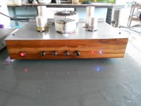
Two BD139 diodes are on main heatsink with outputs, rail voltage +/-35V
Regards
Two BD139 diodes are on main heatsink with outputs, rail voltage +/-35V
Regards
Thank you ,it's clear now ....🙂
Regards,Alex
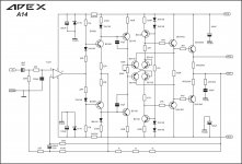
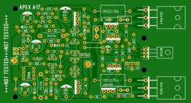
A14
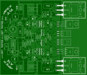
Here is a very first draft for the A14. There is still a lot of potential for optimization and it is not checked for errors. Tonight I'm going to check everything and make it look a little nicer. The size should be a maximum of 70 x 90 mm. Instructions are very welcome.
regards Olaf
Here is a very first draft for the A14. There is still a lot of potential for optimization and it is not checked for errors. Tonight I'm going to check everything and make it look a little nicer. The size should be a maximum of 70 x 90 mm. Instructions are very welcome.
regards Olaf
Attachments
Birg,
your sch shows two Ground Symbols.
Can you say which are Signal Ground/Return, or Power Ground, or Chassis?
your sch shows two Ground Symbols.
Can you say which are Signal Ground/Return, or Power Ground, or Chassis?
Here is a very first draft for the A14. There is still a lot of potential for optimization and it is not checked for errors. Tonight I'm going to check everything and make it look a little nicer. The size should be a maximum of 70 x 90 mm. Instructions are very welcome.
regards Olaf
Nice draft,
Regards
- Home
- Amplifiers
- Solid State
- 100W Ultimate Fidelity Amplifier