The more capacitance you can get, as close as you can get it, the better. If there's enough capacitance on the PCB, you can omit some of the capacitors after the rectifier. Having only decoupling on the PCB, now that is what hardly makes any sense. You probably throw away a good 20db or so of PSRR when you do that.
I'm asking why there is 3,000uf added to the each rail and then three additional 100uf and two 100n on each rail. Is Alex trying to make up for a weak power supply? Does this design really need all that extra filtering, and if so why? I'm just trying to learn something here.
Thanks, Terry
Designers rarely put "detailed" capacitor arrangement in an amplifier circuit design. It is usually part of "implementation", because of dependency on cost, cap type, space, PCB trace, etc. etc.
Smaller caps (lower ESR) are usually better with HF, such that with the same brand, 1000uF+1000uF+1000uF tends to sound better than a single 3000uF. Also, if output transistors are many, each cap can be installed close to each transistor.
Also there is benefit of paralleling with smaller value (usually 1/1000) with the smallest being MKP. But the better the big cap, you don't need the extra smaller caps.
As for the 100n caps, on bipolar output transistor, I'm not sure they are needed. Especially when Black Gate is used.
Power supply is part of the amplifier. An important part actually. Even if the amp has good PSRR, the better the PS, the better the result. It's just about cost per improvement.
Last edited:
Do you believe you can hear the difference with all these extra caps? I may try it both ways though I will not be buying black gate caps for an amp that will likely join the other twenty some unfinished amps in the cabinet. 😱😱
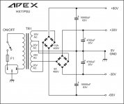
Does anyone have an answer for this?Next question is there are two trimpots on the schematic. One is listed as 4k7 and the other 220R. Are those center values or are we supposed to find trimmers in those values?
Blackgate caps are not needed to demonstrate the improvement in performance when the power transistors are close to the reservoirs. The umbilical to the PSU has much more inductance and resistance than the lytic does. Pretty much any large lytic would be better than none. I never said you needed a lot of caps, just that you needed to put some of them next to the power transistors.
At any rate, it's a very simple rule to make a pretty large improvement in the measured performance of the amplifier, and will also improve stability. In terms of amplifier design, it's a large gain for very little effort.
At any rate, it's a very simple rule to make a pretty large improvement in the measured performance of the amplifier, and will also improve stability. In terms of amplifier design, it's a large gain for very little effort.
Last edited:
Hi all ,merry Christmas's !!!Yes ,my Sprint program has generated a list ,maybe will help ....🙂
Regards,Alex

Thank's a lot Mr Alex for the list it will be very helpful !!
I've always thought of the addition of local reservoir caps in the following manner,
If I had a good supply with lots of capacitors and a big transformer, but the amplifier circuit itself was far from the amp board, then I would have wires joining the two boards.
It's kind of like sipping from a large dam with a straw, no matter how thick the straw, there can come a time when I take a very big sip, that the straw restricts the flow.
I've thought of the local reservoir caps as giving a quick source of current during those fast transients. But since they do close they don't have the restriction of those long wires that connect the amp circuit to the power supply
I've thought of the local reservoir caps as giving a quick source of current during those fast transients. But since they do close they don't have the restriction of those long wires that connect the amp circuit to the power supply
Agree ......😉
I never built A23.Hi Guys,
I started populating the A33 today. I'm using Alex's layout above. The first question I have is why there are over a dozen caps added to the circuit. Is there something wrong with Mile's design? I saw some of this with the A23 that olafk posted but his one has a least 16 caps added that are not on the schematic. Are you guys amplifier designers? Why all the changes to Mile's designs before they are even built?
Next question is there are two trimpots on the schematic. One is listed as 4k7 and the other 220R. Are those center values or are we supposed to find trimmers in those values?
Thanks, Terry
regards Olaf
Hi Guys,
I started populating the A33 today. I'm using Alex's layout above. The first question I have is why there are over a dozen caps added to the circuit. Is there something wrong with Mile's design? I saw some of this with the A23 that olafk posted but his one has a least 16 caps added that are not on the schematic. Are you guys amplifier designers? Why all the changes to Mile's designs before they are even built?
Thanks, Terry
Hi Terry,
Nobody force you to use my layout 🙄 I'm not amplifier designer I do not claim this , I'm a modest PCB designer ,maybe not even a good one ,sorry for inconvenient . In the future I will not offering such bad layout with so many capacitors on PCB 😱
Marry Chritmas ,Alex
Last edited:
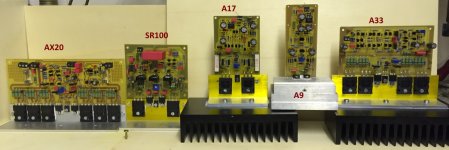
Here are my last amplifiers. There is not one in which a capacitor is more on it as in the specification of Mile. Please be careful in the choice of your examples.Hi Guys,
I started populating the A33 today. I'm using Alex's layout above. The first question I have is why there are over a dozen caps added to the circuit. Is there something wrong with Mile's design? I saw some of this with the A23 that olafk posted but his one has a least 16 caps added that are not on the schematic. Are you guys amplifier designers? Why all the changes to Mile's designs before they are even built?
Next question is there are two trimpots on the schematic. One is listed as 4k7 and the other 220R. Are those center values or are we supposed to find trimmers in those values?
Thanks, Terry
regards Olaf
Attachments
Hi Terry,
Nobody force you to use my layout 🙄 I'm not amplifier designer I do not claim this , I'm a modest PCB designer ,maybe not even a good one ,sorry for inconvenient . In the future I will not offering such bad layout with so many capacitors on PCB 😱
Marry Chritmas ,Alex
I don't think he's saying there's a problem with the design. He's just trying to figure out what the extra caps do.
i have told him and even posted schematic with aditional capacitors,a few other people in last 10-15 posts tried to explain too.
.
all that was needed was to read those posts. neither Alex-MM, or Olaf.k or me are trying to change anything on amp- it self,only to add a capacitor or two since the place was born on pcb while drawing it. why not to put it there if it can be helpfull? it will perhaps do nothhing or very little in some cases, but on a few it will do s lot.
.
i draw pcb with lot of effort,Olaf and Alex MM do them much easier,more compact and nicer to an eye. either one you chose it will work,they were all proven to be done right. no one forces you to put on any of those pcb's anything that is not posted on schematic, mostly because it will end in a pile of...i don't know,why even bother doing DIY?
.
all that was needed was to read those posts. neither Alex-MM, or Olaf.k or me are trying to change anything on amp- it self,only to add a capacitor or two since the place was born on pcb while drawing it. why not to put it there if it can be helpfull? it will perhaps do nothhing or very little in some cases, but on a few it will do s lot.
.
i draw pcb with lot of effort,Olaf and Alex MM do them much easier,more compact and nicer to an eye. either one you chose it will work,they were all proven to be done right. no one forces you to put on any of those pcb's anything that is not posted on schematic, mostly because it will end in a pile of...i don't know,why even bother doing DIY?
Last edited:
Hi Terry,
Nobody force you to use my layout 🙄 I'm not amplifier designer I do not claim this , I'm a modest PCB designer ,maybe not even a good one ,sorry for inconvenient . In the future I will not offering such bad layout with so many capacitors on PCB 😱
Marry Chritmas ,Alex
Hi Alex,
I'm sorry if I asked that wrong. I am only trying to learn. When I see a layout that differs from the schematic I want to understand why. Please don't take offence. I think it is wonderful that you so freely share your work with us. I certainly didn't mean to imply that your layout is bad. I just wanted to understand why you added parts to the circuit. When I am assembling a board I will have printouts of the schematic and parts layout in front of me so I can double check that I am getting everything right. When the two don't agree I start reading back through the thread to see if I can find out why the circuit was changed. You never mentioned that you added anything to the circuit or why so I asked. You haven't explained why you added so many caps so I guess you agree with the explanations that others have given.
Hi olaf,
Sorry, I should have looked more carefully. I built the A9, A17 and A23 last month. I forgt who's layout was who's.
I will try to be more careful with how I ask questions in the future.
Blessings, Terry
On the topic of capacitors here's a link, this guy at eevblog is a oddball, but informative.
EEVblog #33 http://www.youtube.com/watch?feature=youtu.be&v=xlvqUts9H9c
Regards
EEVblog #33 http://www.youtube.com/watch?feature=youtu.be&v=xlvqUts9H9c
Regards
 Merry Christmas to all and all the best!
no one forces you to put on any of those pcb's anything that is not posted on schematic, mostly because it will end in a pile of...i don't know,why even bother doing DIY?
I can't speak for anyone else, but I do DIY because I love building things and have always been fascinated with electronics. If I had an outlet for completed amps I would build cases for each of them but I have a stack of amps now that I will likely die with so most of the PCBs I build end up in the cabinet once I've tested and listened to them for a couple days. You guys have been producing so many layouts lately that I haven't even had time to do much testing. Within the last month or so I have built a pair each of the A9, A17, A23 and now the A33. Once I finish the A33 I hope to take a few days and hook them up to my A/B setup and give them some good comparative listening.
My understanding is that this is a DIY discussion forum. Asking questions that spur discussion shouldn't be a bad thing.
Vostro,
Thanks for the link. I enjoyed that video and will be checking out his other offerings as well
Today is Christmas eve so my house will be filled with family, love and fun for the next couple of days.
Blessings to all of you and I hope you have a very merry Christmas!
it is not bad to ask,but you also need to read answers... 🙂
merry christmas to all the folks that celeborate it !
health,happiness,love,and some money for DIY to all of us! 🙂
merry christmas to all the folks that celeborate it !
health,happiness,love,and some money for DIY to all of us! 🙂
- Home
- Amplifiers
- Solid State
- 100W Ultimate Fidelity Amplifier