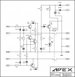
A33 it's playing now ..... 😀 https://www.youtube.com/watch?v=SY3G4ZfwabA
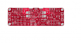
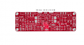
I't was , one error which was corrected (forgot 100K resistor ) . Real tested PCB
attached below 🙂 ,more comments tomorrow .
Regards ,Alex
Nice work,
Regards
Hm.
Ok, a new challenge 🙄
regards Olaf
Stereo protect for A17,
Regards
Attachments
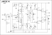
A17 with PRO out pin
A17 audio amplifier is very similar with my project: MicroSOUND-100 (see attach below). However, I believe that A17 is not optimized. Convince yourself that, try make a comparison with my MicroSound 100 project - here's a question for you: in your A17 project, see VAS circuit, there is a 470pF capacitor in parallel with a resistor of 1Mohm. You're sure the other 1Mohm resistor from VAS does not need a capacitor too? Maybe not, if you're going to make a comparison with a Marantz MM7025 (and sure you did that). But are you sure really do not need? You did a rectangular signal test to see what happens if you mount a capacitor in parallel with that resistor? I don't believe you did, considering the result presented.
Attachments
A17 audio amplifier is very similar with my project: MicroSOUND-100 (see attach below). However, I believe that A17 is not optimized. Convince yourself that, try make a comparison with my MicroSound 100 project - here's a question for you: in your A17 project, see VAS circuit, there is a 470pF capacitor in parallel with a resistor of 1Mohm. You're sure the other 1Mohm resistor from VAS does not need a capacitor too? Maybe not, if you're going to make a comparison with a Marantz MM7025 (and sure you did that). But are you sure really do not need? You did a rectangular signal test to see what happens if you mount a capacitor in parallel with that resistor? I don't believe you did, considering the result presented.
VAS transistors colectors are shorted thru 10uF for HF and another 470pF will be in parallel (there will be 940pF), two 220pF can be on both 1M resistors in parallel if you want simetry.
Regards
As always I'm helpful and all attached below 😎 It's 100 % testedLooks great Alex! Will you please post the foil as well?
Blessings, Terry
......

Regards,Alex
Attachments
Last edited:
Hi Alex,
Thank you. One question. Are you running a jumper wire under the board to connect the two output jacks?
Thanks, Terry
Thank you. One question. Are you running a jumper wire under the board to connect the two output jacks?
Thanks, Terry
As always I'm helpful and all attached below 😎 It's 100 % tested
......
Regards,Alex
Thank you for this files... sound A33 vs A23?
Regards
As always I'm helpful and all attached below 😎 It's 100 % tested
......
Regards,Alex
Thank you

Hey merry Christmas's and many good diy built amps to all of you !! 
Now during holidays I will have time to built an amp and I want to give it a try with Mr Apex amps. Does any anyone have the bom list for A23 OR A33 ?
Now during holidays I will have time to built an amp and I want to give it a try with Mr Apex amps. Does any anyone have the bom list for A23 OR A33 ?

Was my plesaure to build this amplifiers .Thank you for this files... sound A33 vs A23?
Regards
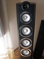
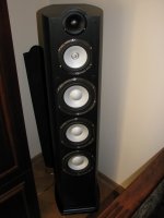
No doubt, both sound very good ,but the winner is A33 😎 I will test on my new Taga Harmony Platinum F120 speakers ......😀
Regards,Alex
Attachments
Last edited:
Was my plesaure to build this amplifiers .
No doubt, both sound very good ,but the winner is A33 😎 I will test on my new Taga Harmony Platinum F120 speakers ......😀
Regards,Alex
Thank you, some people prefer A23 but speakers is most important for real sound test,
Regards
Hi Guys,
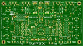
I started populating the A33 today. I'm using Alex's layout above. The first question I have is why there are over a dozen caps added to the circuit. Is there something wrong with Mile's design? I saw some of this with the A23 that olafk posted but his one has a least 16 caps added that are not on the schematic. Are you guys amplifier designers? Why all the changes to Mile's designs before they are even built?
Next question is there are two trimpots on the schematic. One is listed as 4k7 and the other 220R. Are those center values or are we supposed to find trimmers in those values?
Thanks, Terry
In schematics it's usually not necessary to specify exactly what caps to use in the power supply. Most DIYers can choose their own PSU or do a PSU project for however many watts the amp is.
On a PCB, there should be lytics as close as possible to the power BJTs, Alex's layout is smart in this regard. If anything this is what should be specified on the schematic, to place reservoirs very close to the outputs.
On a PCB, there should be lytics as close as possible to the power BJTs, Alex's layout is smart in this regard. If anything this is what should be specified on the schematic, to place reservoirs very close to the outputs.
In schematics it's usually not necessary to specify exactly what caps to use in the power supply. Most DIYers can choose their own PSU or do a PSU project for however many watts the amp is.
On a PCB, there should be lytics as close as possible to the power BJTs, Alex's layout is smart in this regard. If anything this is what should be specified on the schematic, to place reservoirs very close to the outputs.
I'm not asking about the power supply. I'm asking why there is 3,000uf added to the each rail and then three additional 100uf and two 100n on each rail. Is Alex trying to make up for a weak power supply? Does this design really need all that extra filtering, and if so why? I'm just trying to learn something here.
Thanks, Terry
- Home
- Amplifiers
- Solid State
- 100W Ultimate Fidelity Amplifier