Hi,
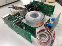
Here I am having lots of fun with my friends. I shared PCBs that I designed with them, fairly good DartZeel design.
Just finished the soldering work, and preparing to make them sing!
They look awesome!
Hi!
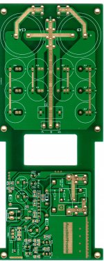
Some time ago I bought a couple of the PCBs shown here earlier, from eBay possibly.
View attachment 766184
I also bought the servo board. Then nothing happend for a while, since other project took my time.
Recently I discovered a new (to me) PCB on Taobao where the servo was included on-board, togehter with 3 output pairs.
View attachment 766185
So now I have ordered a new pair of PCBs and may give it a try. If anyone is interested in my old set of boards including the servos, I will send them for free.
Cheers,
Morten
I would love to buy from there but do not understand anything off Chinese.
They look awesome!
Thank you!
")
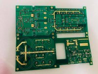
As you can see, there are 2 AVX supercapacitors on the PCB, so it's not NHB-108. Guess which circuit it is ?

Hi!
Some time ago I bought a couple of the PCBs shown here earlier, from eBay possibly.
View attachment 766184
I also bought the servo board. Then nothing happend for a while, since other project took my time.
Recently I discovered a new (to me) PCB on Taobao where the servo was included on-board, togehter with 3 output pairs.
View attachment 766185
So now I have ordered a new pair of PCBs and may give it a try. If anyone is interested in my old set of boards including the servos, I will send them for free.
Cheers,
Morten
Hi
I sent you a PM...
Hi,
Here I am having lots of fun with my friends. I shared PCBs that I designed with them, fairly good DartZeel design.
Just finished the soldering work, and preparing to make them sing!
Those PC boards will be available for DIY interests?
Thanks
Those PC boards will be available for DIY interests?
Thanks
Forget to attach the picture the mentioned PC boards
Attachments
Forget to attach the picture the mentioned PC boards
Hi all,
Well, I got several PM about the PCB releasing.
Right now, I am doing prototyping to ensure everything is alright.
As you can see, I designed an add-on module compatible with 458 main board.
The module includes filter caps, and also protection circuit/relay based on uPC1237, quite a nice protection IC.
About the thump, no idea about it right now, I did observe some in the simulation, but I guess prolonging relay off-ON time would just be fine.
Maybe I could start a GroupBuy here in DIYaudio? Please let me know if you're interested.
Anyway, please be patient, after the prototype board is good, I will start to release.
Best,
Erik
Attachments
Thank you!
As you can see, there are 2 AVX supercapacitors on the PCB, so it's not NHB-108. Guess which circuit it is ?
Hehe, I'm not that familiar with these circuits...
What's there to patent, the circuit as such...?
Should we not take that circuit with a pinch of salt?
The above obviously concerns the 458 circuit only.
What's there to patent, the circuit as such...?
There is a term for this: "vanity patent". It provides the patent holder with no hope to ever defend it in court or God forbid, sell it. Yet, it improves their self esteem and is an amusing and perhaps cheaper alternative to advertising.
I just wish the Patent Office would mark such patents with special colours, perhaps even with a rainbow

Vanity Patents: just_n_examiner — LiveJournal
There is an interesting factory visit at Dartzeel plant.
Michael Fremer, which own NHB-18NS and NHB-458 talks with Herve from Dartzeel.
There is some nice clips from the inside of the 458/468.
YouTube
Hi is selling just expensive hardware, and what he said about negative feedback it's technical nonsens.
.Anybody know how to make feedback on this amp? I have the 2 pair output version. I really think it is a lousy amp.
If you maybe tell us more about how you implemented it, what kind of power stage you used and what kind of preamp you piloted it with, then maybe someone can try to give you some indication.
.
Then this project was born and it is characterized by not having any negative global feed-back ring.
.
Making one means distorting it and you should definitely devote yourself to some other circuit layout.
.
Know that in the last three years I have made two of them (the first with a pair of BJTs and the second with two pairs of BJTs for each channel) and they sound wonderfully good with all the speakers with which it has been tested.
.
Here in Italy, in a network of enthusiasts, dozens of people have used it with great satisfaction.
The first with only one set Mosfet was much better. But again maybe there is fake components. Never again amplifier moduls from China. Sound is very boring without attack.
Mosfet? You sure you're in the right thread?
Only broke students buy modules from China. What did you expect?
- Home
- Amplifiers
- Solid State
- Dartzeel amp schematic - build this?