Update to F7 simulation
I have created a small bug in the previous setup: When switching from 8 to 4 Ohms output load, I have short-circuited the feedback resistor R7.
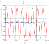
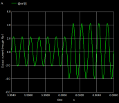
With the corrected schematic the output power at 8 Ohms is 24 W, at 4 Ohms it is 46.5 W.
The graph attached shows the input, output and feedback signals around the switching point at 6s. The change in output voltage amplitude is barely visible. This probably leeds to a very good damping factor.
I have created a small bug in the previous setup: When switching from 8 to 4 Ohms output load, I have short-circuited the feedback resistor R7.
With the corrected schematic the output power at 8 Ohms is 24 W, at 4 Ohms it is 46.5 W.
The graph attached shows the input, output and feedback signals around the switching point at 6s. The change in output voltage amplitude is barely visible. This probably leeds to a very good damping factor.
Attachments
Last edited:
Pass Labs F6 modified simulation
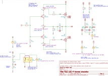
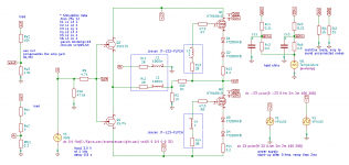
This is a modification of the Pass Labs F6 amplifier.
The output transistors are IXYS depletion NMOS Power FETs.
The transistor bias is generated by a source resistor and two diodes in series.
A transformer with four windings is powered by the JFET driver on winding 2. Windings 3 and 4 are used to drive the Power MOS (as in F6). Positive feedback derived from the ouput current has been introduced in the F7. Here this feedback is applied via winding 1 of the transformer. The negative feedback is by the usual R1/R2 resistor divider. Thus both feedback loops may be tailored independently from each other and from the input.
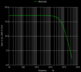
This is still a simulation study only. Some results are shown in the pictures. The output power is 24 W (8 Ohm) and 45 W (4 Ohm) with 1% THD (mostly third harmonics). The damping factor is 46, the output resistance 0.17 Ohm.
The simulation setup is still not complete:
The IXTH16N10 VDMOS model parameters are crude.
The transformer model is ideal and thus overly simplified.
The smaller, more cost efficient IXTH6N50D2 transistors may be adequate.
The diodes are still generic. Diotec FT2000KB may be o.k.
This is a modification of the Pass Labs F6 amplifier.
The output transistors are IXYS depletion NMOS Power FETs.
The transistor bias is generated by a source resistor and two diodes in series.
A transformer with four windings is powered by the JFET driver on winding 2. Windings 3 and 4 are used to drive the Power MOS (as in F6). Positive feedback derived from the ouput current has been introduced in the F7. Here this feedback is applied via winding 1 of the transformer. The negative feedback is by the usual R1/R2 resistor divider. Thus both feedback loops may be tailored independently from each other and from the input.
This is still a simulation study only. Some results are shown in the pictures. The output power is 24 W (8 Ohm) and 45 W (4 Ohm) with 1% THD (mostly third harmonics). The damping factor is 46, the output resistance 0.17 Ohm.
The simulation setup is still not complete:
The IXTH16N10 VDMOS model parameters are crude.
The transformer model is ideal and thus overly simplified.
The smaller, more cost efficient IXTH6N50D2 transistors may be adequate.
The diodes are still generic. Diotec FT2000KB may be o.k.
Attachments
-
 F6mod-fft-1kHz-8-Ohm.png9.1 KB · Views: 215
 -
 F6mod-phase.png9.5 KB · Views: 189
 -
 F6mod-gain.png9.1 KB · Views: 218
 -
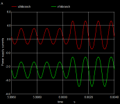
 F6mod-load-currents-8-4-Ohm.png11.5 KB · Views: 176
 -
 F6mod-supply-currents-8-4-Ohm.png11.5 KB · Views: 179
 -
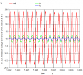 F6-mod-in-out-fb.png14.3 KB · Views: 322
 -
 F6mod-Power-temperature.png11.2 KB · Views: 340
 -
 F6mod-circuit.png29.7 KB · Views: 330
Update to Pass Labs F6 modified simulation
I have replaced the generic diode model by a vendor (Diotec AG) supplied model for the power diode FT2000KB.
The new simulation data for output load 8 Ohm are:
Power 24 W with THD 0.3%, mostly third harmonic, damping factor 69, output rsistance 0.12 Ohm .
The new simulation data for output load 4 Ohm are:
Power 45 W, THD 0.65%, mostly third harmonic
Attachments
OSs for ngspice
ngspice is plain C code, running on many operating systems.
The couple KiCad/ngspice (KiCad as schematic entry, ngspice as simulation engine) is distributed and maintained under Linux, MS Windows and macOS.
ngspice is plain C code, running on many operating systems.
The couple KiCad/ngspice (KiCad as schematic entry, ngspice as simulation engine) is distributed and maintained under Linux, MS Windows and macOS.
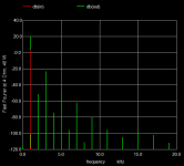
Improved fft measurements on the modified F6
There has been a recent thread about Fast Fourier Transform (fft) here in diyaudio (how to measure precisely distortion with LTspice?). What I have learned from this thread is that one has to be very careful when defining fft measurements on (amplifier) simulation data.
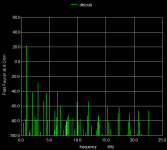
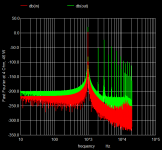
Therefore I have revised the fft simulations that were shown above for the modified F6 amplifier. Now we do an extra simulation run per output resistance (8 and 4 Ohm) dedicated to the fft and THD measurements only. The transient simulation time step has been aligned to the input voltage period. The background noise of the input voltage has been determined. The dc offset has been subtracted from the signal (detrending).
The resulting fft measurements are shown in the pictures. The background numerical noise is now 200 dB below the signal. The harmonics are clearly seen and are far above the noise level.
There has been a recent thread about Fast Fourier Transform (fft) here in diyaudio (how to measure precisely distortion with LTspice?). What I have learned from this thread is that one has to be very careful when defining fft measurements on (amplifier) simulation data.
Therefore I have revised the fft simulations that were shown above for the modified F6 amplifier. Now we do an extra simulation run per output resistance (8 and 4 Ohm) dedicated to the fft and THD measurements only. The transient simulation time step has been aligned to the input voltage period. The background noise of the input voltage has been determined. The dc offset has been subtracted from the signal (detrending).
The resulting fft measurements are shown in the pictures. The background numerical noise is now 200 dB below the signal. The harmonics are clearly seen and are far above the noise level.
Attachments
If this software is for Linux OS, does it function on Androide based pads ?
There are commercial simulators with schematic entry available for Android tablets using ngspice as their simulation engine, see WeSpice (Our Apps) or CircuitSafari (Logipipe, LLC).
ngspice (experimental) will read, simulate and write wav audio files
There is now an (experimental) ngspice that reads, simulates and write wave audio files.
ngspice git branch wav-audio has the sources that compile with MSVC or Linux.
The following example is for Windows user only. Please download Spice_wav from http://ngspice.sourceforge.net/experimental/Spice_wav.7z and expand it into folder C:\
The attached PassLabF6-diyaudio-5.zip contains the modified F6 amplifier. In the example it will read a short wav file gits.wav with a guitar riff from C:\Spice_wav\exampleswav, use the resulting waveform as input signal of the amp, amplify the signal and store it back to C:\Spice_wav\exampleswav\git-f6-1.wav. In this file the left channel is the original sound, the right channel is the amplified signal, cut down by the amplification factor with a resistive divider.
The example is started by opening KiCad/Eeschema 5.1.6, loading file F6thermal-min-compacted.sch. You will see the circuit diagram of the amplifier. The simulation is then started by
Tools -> Generate Netlist File... -> Spice -> Default Format -> Simulator Command: C:\Spice_wav\bin\ngspice.exe -> Run Simulator
External ngspice is called, loading automatically the circuit netlist and the simulation script script5.txt. The simulation is running, and when ready, the output file git-f6-1.wav with its two channels has been generated.
How to define the special input command
(attached to the input voltage source V3), and the ouput
is described on the web pages of by Robin Gareus at oss:spicesound:start [Robin Gareus].
For reading and writing wav, ngspice is using the libraries libsamplerate and libsndfile.
Things are still experimental, and much more testing and more experience may be needed to optimize ngspice and wav i/o.
There is now an (experimental) ngspice that reads, simulates and write wave audio files.
ngspice git branch wav-audio has the sources that compile with MSVC or Linux.
The following example is for Windows user only. Please download Spice_wav from http://ngspice.sourceforge.net/experimental/Spice_wav.7z and expand it into folder C:\
The attached PassLabF6-diyaudio-5.zip contains the modified F6 amplifier. In the example it will read a short wav file gits.wav with a guitar riff from C:\Spice_wav\exampleswav, use the resulting waveform as input signal of the amp, amplify the signal and store it back to C:\Spice_wav\exampleswav\git-f6-1.wav. In this file the left channel is the original sound, the right channel is the amplified signal, cut down by the amplification factor with a resistive divider.
The example is started by opening KiCad/Eeschema 5.1.6, loading file F6thermal-min-compacted.sch. You will see the circuit diagram of the amplifier. The simulation is then started by
Tools -> Generate Netlist File... -> Spice -> Default Format -> Simulator Command: C:\Spice_wav\bin\ngspice.exe -> Run Simulator
External ngspice is called, loading automatically the circuit netlist and the simulation script script5.txt. The simulation is running, and when ready, the output file git-f6-1.wav with its two channels has been generated.
How to define the special input command
Code:
dc 0.0 file(C:/Spice_wav/exampleswav/gits.wav) snd(0 0 0.5 0 0 32)
Code:
sndparam git-f6-1.wav 48000 wav32 3.5 0.0 2
  tran 6.5104166e-07 3.0 0.1 6.5104166e-07
sndprint v(in) v(wout)For reading and writing wav, ngspice is using the libraries libsamplerate and libsndfile.
Things are still experimental, and much more testing and more experience may be needed to optimize ngspice and wav i/o.
Attachments
Last edited:
There is a small (but growing) collection of KiCad/Eeschema/ngspice examples of (audio) amplifiers at https://forum.kicad.info/t/simulation-examples-for-kicad-eeschema-ngspice/34443 . KiCad/Eeschema serves for schematic entry, ngspice for simulation.
- Home
- Design & Build
- Software Tools
- Installing and using ngspice - an opensource simulator