Yes but why does it move all the way to the right side when entering a number other than 0? This is a bit confusing but not a big deal. When you say not needed for conventional speakers, do you mean it is not necessary to adjust for the offset tweeter?Normally X=0 is in the middle
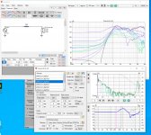
View attachment 1034144
Anyway, this window is primarily for designing line arrays. Should not be needed with conventional speakers with few drivers easy to handle without any visualization.
Anyway this is just nitpicking, thank you for
this fantastic software kimmosto!
Last edited:
Member
Joined 2003
I honestly don't use that "driver layout" window, just enter the coordinates into the driver configuration on the crossover and be done with it. The Layout section is more for arranging of many drivers like line array or CBT so it can do some calculations for you.
I guess almost no one uses that window for others than line arrays so there's not much pressure to optimize auto scaling of front view to symmetrical. Fixing 0 to the middle would be very easy.Yes but why does it move all the way to the right side when entering a number other than 0? This is a bit confusing but not a big deal. When you say not needed for conventional speakers, do you mean it is not necessary to adjust for the offset tweeter?
Sorry about all the newbie questions, but after using the software more it is all starting to sink in now and make sense ")
Got it, so I don't have to worry about the driver layout window.
But just to be clear, I still have to let the software know the positions for all drivers relative to eachother? Entering coordinates into driver config like Dcibel says. I was initially thinking the software has all the info in needs via the measurements. But they are just isolated measurements, so the software still needs to know where the drivers are in relation to eachother.
Member
Joined 2003
Member
Joined 2003
Thank you, it worked!When exporting multiple driver IR response, to keep relative amplitude between drivers, do not export as PCM data, choose a different file format.
Member
Joined 2003
^^ the reference channel has DC error in the input which makes the low end rise. There is DC correction / fix in VituixCAD IR to FR tool.
At least this was case with my RME babyface interface if I used xlr cable with the loopback there was this kind of DC error. Apparently there is some DC on the interface outputs. RME provides separate loopback mode in the virtual mixer, which I guess makes the loopback in digital domain. Kimmosto suspected this is not enough to cancel USB related time delay problems but in my view it has been working ok, no apparent time issues with it. I guess the loopback happens at the device (includes the USB communication delay) and not on the computer (before USB) and thus works.
edit. M4 seems to have Loopback feature as well, not sure how it is implemented though. You could try it if IR / FR tool DC removal is not effective and you need to make new set of measurements. https://cdn-data.motu.com/manuals/usb-c-audio/M_Series_User_Guide.pdf
Member
Joined 2003
That’s a good point, the monitor/mix knob needs to be fully cranked over to “playback”.edit. M4 seems to have Loopback feature as well, not sure how it is implemented though. You could try it if IR / FR tool DC removal is not effective and you need to make new set of measurements. https://cdn-data.motu.com/manuals/usb-c-audio/M_Series_User_Guide.pdf
Member
Joined 2003
I have a question about "export polar frequency responses" from the file menu:
when I use this I cannot manage to export the vertical polars whatever I try. The application says: "exported 98 reponses", but in the folder there are only half that number , all starting with H.
Could it be that the verticals are overwritten with the Horizontals, or am I missing some setting maybe?
Thanks!
Kees
I found it; it depends in the parsing settings in the options screen; if H and V aren't both defined, only His exportedI have a question about "export polar frequency responses" from the file menu:
when I use this I cannot manage to export the vertical polars whatever I try. The application says: "exported 98 reponses", but in the folder there are only half that number , all starting with H.
Could it be that the verticals are overwritten with the Horizontals, or am I missing some setting maybe?
Thanks!
Kees
April Fool's Day revision is out....am I missing some setting maybe?
2.0.85.0 (2022-04-01)
Main- Added 'Copy biquad coefficients' window. User can include/exclude block type, biquad numbering, buffers, a0, parameter/coefficient name, value as decimal, value as 8.24 hex and comma (end of line). Selected (partial) text can be copied. Direct export as text file. Variables in template text file (.vxt) can be replaced with biquad coefficients and buffer parameters.
- Added 'Platin SM 48k' to DSP system list in Options window.
- Polar frequency response export uses file naming selected in Options: Generic 2D, CLIO 3D, EASE 3D, VACS 3D, MF 2D or MF 3D.
- X=0mm is centered in front view of Driver layout window.
- Enclosure tool opens with default driver configuration: driver count=1, isobaric=no, extra mass=0 g, output resistance=0 Ohms, to avoid wrong result due to unwanted value from previous session.
- " mrg" is not anymore added to the end of filenames to support balloon (3D) naming formats. Program refuces to save merged files to the same directory with far field HF responses if file extension is not changed txt->frd or frd->txt.
- Directivity export uses file naming selected in Options: Generic 2D, CLIO 3D, EASE 3D, VACS 3D, MF 2D or MF 3D.
- Response file writer compresses .cal and .mic files by skipping frequency points where magnitude slope changes less than 0.12 dB/oct.
At least one point per octave and first and last point are written though response is perfectly flat. Feature is easiest to use with Calculator tool.
Microsoft does not support and distribute .NET 4.0 anymore, and uninstalling VS 2019 will remove also development tools for .NET 4.0 from my PC.
Next VituixCAD revisions (2.0.85.1...) will require .NET 4.5.2 and Windows 7 sp1 or later. XP users should upgrade directly to Win10 imho.
This brings also some new possibilities such as project packing without external tools.
Next VituixCAD revisions (2.0.85.1...) will require .NET 4.5.2 and Windows 7 sp1 or later. XP users should upgrade directly to Win10 imho.
This brings also some new possibilities such as project packing without external tools.
- Home
- Design & Build
- Software Tools
- VituixCAD