Just found from archives that 5 years ago NeoCD 3.0 was measured at 100 cm with (CLIO) MLS without protection capacitor. Maximum SPL 85 dB/1m = voltage was 10 dB below 2.83 V. Amplifier Arcam FMJ A38 which can handle zero load if current is low enough.
One option probably not mentioned is to:
1) Measure impedance response
2) Design simple filter for protection with VCAD, with impedance response but without acoustic frequency responses. Component values should be accurate. Could be e.g. 2nd order HP at final XO frequency / 2.
3) Select driver and File -> Export -> Filter response on driver
4) Build protection filter, connect and measure acoustical responses 0-180 hor & ver. Use normal semi-dual connection, reference from output of sound card or amplifier.
5) Post process measurements with Calculator: acoustical responses (A) divided by Filter response on driver (B).
6) Optionally trim LF and extend HP slope manually with Minimum phase function, Maintain delay (at ~2 kHz) checked to avoid damaging timing /phase too much with MP. But this does not work with dipoles due to MP.
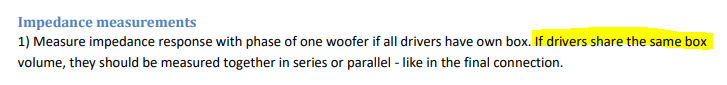
“If impedance response was measured from group of drivers in common volume and drivers are entered to crossover as a single driver (as recommended), scaled impedance response should represent single driver.” - VituixCAD_Help_20
When drivers share the same box (2,5 way) and I measure impedance like in a final connection do I have to scale impedance of bass drivers in Driver Tab? If, yes, do I multiply it by 2?
When drivers share the same box (2,5 way) and I measure impedance like in a final connection do I have to scale impedance of bass drivers in Driver Tab? If, yes, do I multiply it by 2?
Last edited:
^Scale by 2.0 if you measure impedance of two drivers in parallel. Scale by 0.5 if you measure Z of two drivers in series. Justification: single driver instance in XO schematic should have impedance of single driver. Very simple I hope.
Indeed it is. Thanks and have a good day.
^If you measure and load just one mid-woofer (representing half of total cone area), you need to divide vent area by 2 to get correct shape, and scale whole LF part by +6.02 dB.
But if you measure both mid-woofers separately and load both cone responses to LF list, you can enter whole vent area or diameter for vent response.
But if you measure both mid-woofers separately and load both cone responses to LF list, you can enter whole vent area or diameter for vent response.
I measured bass-reflex response with both drivers connected parallel. I thought that if I measure just one, the other one would behave as a passive radiator, what will mess the measurement. Wouldn't it?
Is it advisable to measure only woofer separately even though they share one box? Should I press the other one with a pillow, so it doesn't act like passive radiator?
Is it advisable to measure only woofer separately even though they share one box? Should I press the other one with a pillow, so it doesn't act like passive radiator?
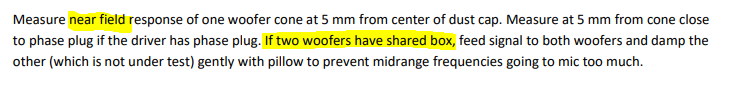
^All drivers sharing the same box volume must be connected to amplifier during near field measurements to get correct shape of LF response and avoid passive radiator effects. This applies also to near field measurements of vents and actual passive radiators and impedance measurement. This is also mentioned in measurement instructions.
But you can near field measure with microphone just one cone (while damping the other(s) gently with pillow to avoid acoustic leak to mic) if you are quite certain that all individuals have the same frequency response. There could be tiny...small differences due to box shape and driver individual and how mic happens to locate close to dust cap or cone.
As already told, measuring all individual radiators (all cones, vents and PRs) with mic helps scaling and creates correct sum especially with actual passive radiators.
kimmosto, if we talk about measuring the impedance of two midwoofers in a common box. Is it correct to connect both to the amplifier, measure both at once and load the response into the input field for any of the midwoofers, and leave the input field of the second blank. ?
Last edited:
filter coeffs
Hello Kimmosto,
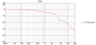
Is there an option in VCad to generate all the filter coeffs in one shot for a filter with a transfer function such as in the attached picture? I could do it in 3 blocks or so separately, but would like to know whether there is a "all in one" coefficients function available.
Hello Kimmosto,
Is there an option in VCad to generate all the filter coeffs in one shot for a filter with a transfer function such as in the attached picture? I could do it in 3 blocks or so separately, but would like to know whether there is a "all in one" coefficients function available.
Attachments
Or short inputs of the second midbass unit.But you can near field measure with microphone just one cone (while damping the other(s) gently with pillow to avoid acoustic leak to mic) if you are quite certain that all individuals have the same frequency response.
Edit: shorting inputs on the second midbass is for far field measuring of a 2.5 system or a system with two midbasses in parallel connection. Near field measuring within 2-3 mm from the membrane center (with both midbass running) is good enough without using pillow.
Last edited:
kimmosto, if we talk about measuring the impedance of two midwoofers in a common box. Is it correct to connect both to the amplifier, measure both at once and load the response into the input field for any of the midwoofers, and leave the input field of the second blank. ?
Usually only one mid-woofers can be added to Drivers tab if manufacturer and type of all mid-woofers are the same. For example line array with nine mid-woofers can have measurement data (frequency responses to 0-180 deg and one impedance response) of single mid-woofer which is linked to all nine driver instances in crossover schematic.
All nine drivers must be connected to amplifier while all near field and impedance response measurements, but only one driver connected to amplifier while far field frequency response measurements 0-180 deg.
Usually only one mid-woofers can be added to Drivers tab if manufacturer and type of all mid-woofers are the same.
Two identical midbasses are located one above the other in the same volume. Measuring 0 degrees, on axis. I measure the frequency response of each by connecting both to an amplifier, but covering the one that is not being measured with a pillow. I measure impedances by connecting the amplifier in turn to each separately, without covering it with a pillow. That is, as a result, there are 2 frequency response curves, 2 impedance response curves. Or should it be different?
Problems installing VituixCad under Windows XP
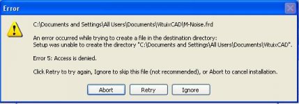
I am getting errors when I try to install VituixCAD under Windows XP. The errors are access issues concerning creating files under C:\Documents and Settings\All Users\Documents\VituixCAD. The Documents folder is inaccessible. I have deleted all files in my Temp folder, but still have problems. Anyone have any suggestions since I can't change the installation paths.
I am getting errors when I try to install VituixCAD under Windows XP. The errors are access issues concerning creating files under C:\Documents and Settings\All Users\Documents\VituixCAD. The Documents folder is inaccessible. I have deleted all files in my Temp folder, but still have problems. Anyone have any suggestions since I can't change the installation paths.
Attachments
Two identical midbasses are located one above the other in the same volume. Measuring 0 degrees, on axis. I measure the frequency response of each by connecting both to an amplifier, but covering the one that is not being measured with a pillow. I measure impedances by connecting the amplifier in turn to each separately, without covering it with a pillow. That is, as a result, there are 2 frequency response curves, 2 impedance response curves.
Everything is wrong assuming that "Measuring 0 degrees, on axis" means far field.
My instructions must be just crap, but all I can say or do is that read again and try try understand. Someone else could try to draw pictures about measurement setup and connections in every step, because text does not work no matter how many times I repeat with different words.
Where is the "online database" option?
Maybe I'm being very blind, but having read the manual and searched for info on the internet including results on this site I cannot for the life of me find where the menu option is in this software to enable the online database.
Can someone please tell me exactly what menu i need to look at to find it.
Two identical midbasses are located one above the other in the same volume. Measuring 0 degrees, on axis. I measure the frequency response of each by connecting both to an amplifier, but covering the one that is not being measured with a pillow. I measure impedances by connecting the amplifier in turn to each separately, without covering it with a pillow. That is, as a result, there are 2 frequency response curves, 2 impedance response curves. Or should it be different?
Attachments

Maybe I'm being very blind, but having read the manual and searched for info on the internet including results on this site I cannot for the life of me find where the menu option is in this software to enable the online database.
Can someone please tell me exactly what menu i need to look at to find it.
Tools > Enclosure > check "online data" on the top row ....
- Home
- Design & Build
- Software Tools
- VituixCAD