I assume I have to know the identity of a suitable VDMOS device in order to pick it from the builtin VDMOS models. Can you please suggest something equivalent to the N-Channel Power MOSFET 600V, 2.0Ω that I'm using?
No idea, it's like looking through a bucket of random screws to find the one you actually want. Alternately you can look through MOSFETs on manufacturer websites and then desperately hope that LTSpice has the one you want.
Alternatively, can I just include the ksubthres=parameter in my existing FDPF5N60NZ model? Of course, then there's the question of what I should set it too. I'm not seeing anything obvious in the datasheet.
A minimum value of ksubthres will reduce the severity of the spikes, but for accuracy it really needs to be curve fitted. You can add ksubthres=0.1 to existing VDMOS models. Sometimes you may end up with too much leakage current though.
What is the mechanism in the simulation by which the turn-off behaviour of the 2 MOSFETs impacts the first stage of the amp?
Without subthreshold conduction, the discontinuity in the conduction curve causes problems for LTspice and this can result in spikes getting into other nodes which they should not. Also Miller capacitance tends to conduct spikes backward through a circuit.
Without subthreshold conduction, the discontinuity in the conduction curve causes problems for LTspice and this can result in spikes getting into other nodes which they should not. Also Miller capacitance tends to conduct spikes backward through a circuit.
Thanks very much!
In fact, they do.
Thanks. I'm only going on what I've read in other threads .
If grid and screen current are indeed modeled well, can you tell me what the problem I posted here is please?
Hi!
a little OT, I installed XVII and at "edit command simulation" I have the issue that transient sim parameters are copied to ac analysis and vice versa, do you know the cure for it?
thank you in advance
It is annoying. I keep all my simulation commands setup and ready to go. All except the one I'm using I turn into a comment. Depending on what analysis I want to do I tun the last active one into a comment (right-click, cancel. click Comment, OK, turns blue) and turn the commented one I wan to use back into a Spice Directive (right-click, click Spice Directive, OK, turns from blue to black).
If grid and screen current are indeed modeled well, can you tell me what the problem I posted here is please?
See More Ruminations on Screen Drive/Crazy Drive
I cannot check the current placing the cursor over the resistor after the sim, it appears big palm instead of dcm
I do not know how but reading the current placing the cursor over the part works now, sorry for inconvinience
I've been having a bit of a tussle with LT in the past week or two in getting a simple 'relay' based circuit to operate correctly.
This all started as an attempt to come up with a simple circuit to make the popular ACA over in the Pass Labs forum silent at power on and power off. I've tried solid state relays and latterly the voltage controlled switch included in LT to operate as a 'short' across the speaker.
Question...
I hit the same problem in all variations and that is that the supposedly closed (contacts normally closed in this version) relay allows the switch OFF thump through.
Is it because the simulated switch relies on a supply voltage being present ?
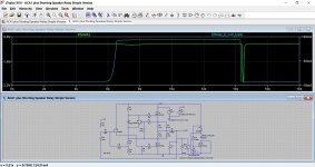
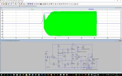
Here is the simulation (all default LT XVII models) of the amplifier. The speaker is R13 and the input voltage to the amp is removed.
Why does this turn off pulse always appear when the relay should be shorted ? Monitoring the current in the speaker (R13) shows the effect well.
Exactly the same happens with series connected solid state relays and drive circuitry carefully configured to turn them off before the supply has even dipped by few volts. The drive to the relay is removed well before the pulse appears.
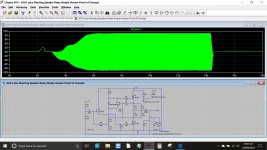
Edit... the second image also shows the supply voltage. You can see how quickly the relay should drop out (and become a short)
This all started as an attempt to come up with a simple circuit to make the popular ACA over in the Pass Labs forum silent at power on and power off. I've tried solid state relays and latterly the voltage controlled switch included in LT to operate as a 'short' across the speaker.
Question...
I hit the same problem in all variations and that is that the supposedly closed (contacts normally closed in this version) relay allows the switch OFF thump through.
Is it because the simulated switch relies on a supply voltage being present ?
Here is the simulation (all default LT XVII models) of the amplifier. The speaker is R13 and the input voltage to the amp is removed.
Why does this turn off pulse always appear when the relay should be shorted ? Monitoring the current in the speaker (R13) shows the effect well.
Exactly the same happens with series connected solid state relays and drive circuitry carefully configured to turn them off before the supply has even dipped by few volts. The drive to the relay is removed well before the pulse appears.
Edit... the second image also shows the supply voltage. You can see how quickly the relay should drop out (and become a short)
Attachments
Thanks for looking Hans
Hmm... so changing those parameters seems to mute the audio all the time (if R11 at the left is reconnected).
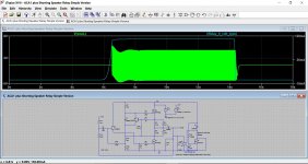
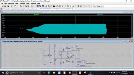
This is the ACA with audio applied. I can't reason out why the relay doesn't short the audio when its drive is removed.
Also shown is Vh=5 and Vt=3 (and vice versa... it gets confusing)
Hmm... so changing those parameters seems to mute the audio all the time (if R11 at the left is reconnected).
This is the ACA with audio applied. I can't reason out why the relay doesn't short the audio when its drive is removed.
Also shown is Vh=5 and Vt=3 (and vice versa... it gets confusing)
Attachments
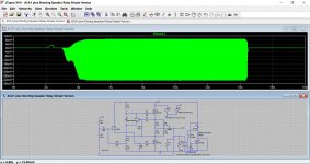
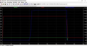
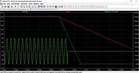
Static control voltage works. Proved. Zero control volts to the switch mutes the audio, 24 volts on the switch unmutes it. That is shown in the first two images.
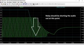
Third image shows the control voltage falling to zero from its initial 24 volts but the switch stays open.
Third image shows the control voltage falling to zero from its initial 24 volts but the switch stays open.
Attachments
Final one for today.
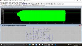
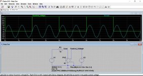
Simple voltage source and shorting relay. The relay is open when the simulation is first run and is not controlled by V2 (and to me it should be).
If you make V2 a constant 24 volts DC the circuit is unmuted. Make it 0 volts and it mutes. So the relay works with static voltages applied. Set V2 back to a pulse and it doesn't.
Don't understand Why does the dynamically changing control voltage not operate the relay ?
Simple voltage source and shorting relay. The relay is open when the simulation is first run and is not controlled by V2 (and to me it should be).
If you make V2 a constant 24 volts DC the circuit is unmuted. Make it 0 volts and it mutes. So the relay works with static voltages applied. Set V2 back to a pulse and it doesn't.
Don't understand
Why does the dynamically changing control voltage not operate the relay ?Attachments
Spice Switches
Mooly,
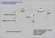
Getting LTspice switches to work is confusing, and the next time you want to use one you forget how to do it. I built subcircuits and symbols to solve this problem.
See attached zip file of a normally open switch and a normally closed switch.
Use as per the attached test circuit. I use the old LTspice, but I expect they will work with the new version. The *.sub files go in the 1sub' directory, and I put the symbols in the `Misc' directory under `sym'.
Regards,
Paul Bysouth
Mooly,
Getting LTspice switches to work is confusing, and the next time you want to use one you forget how to do it. I built subcircuits and symbols to solve this problem.
See attached zip file of a normally open switch and a normally closed switch.
Use as per the attached test circuit. I use the old LTspice, but I expect they will work with the new version. The *.sub files go in the 1sub' directory, and I put the symbols in the `Misc' directory under `sym'.
Regards,
Paul Bysouth
Attachments
- Home
- Design & Build
- Software Tools
- Installing and using LTspice IV (now including LTXVII), From beginner to advanced