Impedance flattening circuits can be useful with amps of high output resistance but you would need to measure the whole speaker, woofer included. Simulation is just a step to figure out ball park values, this should be confirmed with actual parts and then modified if necessary, to be on the safe side. Latest xo version appears ok.
This is exactly the case for me, SET amp, output resistance about 3,5 Ohm. The woofer will be powered from another amp and crossed actively via DSP. The reason why I decided to go this way is that the SET amp is fantastic in the mid-high range, but is not capable of delivering enough energy in bass and midbass section.
I understand the simulation is just a preliminary thing of course and fine tuning will be needed. Anyhow, at some point crossover components must be ordered. I have played some more yesterday and today with values and configuration, but I could not come up with anything better than in the last shared simulation. So perhaps it is time to try.
Sys degrees
Dear all,
noob here - go easy pls!")
I have done my first crossover using these steps:
a) built an enclosure;
b) installed drivers;
c) measured T&W individually with DATS and saved two .zma;
d) measured T&W individually and in parallel with Omnimic and saved three .frd's;
e) imported three .frd's into Xsim;
f) aligned System curve with parallel .frd curve; and
g) designed crossover.
Question:
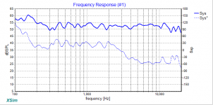
In my image here how do I interpret the Sys degrees (dashed blue) trace?
For this design what is this telling me about my crossover?
Huge thanks to MR Waslo and contributors for these AWESOME software creations!
PS: she sounds great!
Dear all,
noob here - go easy pls!
I have done my first crossover using these steps:
a) built an enclosure;
b) installed drivers;
c) measured T&W individually with DATS and saved two .zma;
d) measured T&W individually and in parallel with Omnimic and saved three .frd's;
e) imported three .frd's into Xsim;
f) aligned System curve with parallel .frd curve; and
g) designed crossover.
Question:
In my image here how do I interpret the Sys degrees (dashed blue) trace?
For this design what is this telling me about my crossover?
Huge thanks to MR Waslo and contributors for these AWESOME software creations!
PS: she sounds great!
Attachments
The frequency response for the individual drivers look odd.
There's also about a 10db difference between the amplitude of the individual drivers plus the frequency response goes negative 50dbspl.
The reason for the phase being wrapped is the 2.5inch offset you have in the tweeter config.
It might be best to redo the measurements.
Do your measurements look similar like the driver datasheets ?
How much signal were you driving the speakers whilst performing the measurements ?
Last edited:
I think the main reason for the "phase wrap" you see is just that you have too much overall delay in the simulation display. (Overall delay is simply a representation/assumption of distance from microphone or ear, it's not a terrible thing or even very meaningful unless it is very different between different drivers).
Any time I'm looking a phase curve, the very first thing I do is go to the Power Amp symbol, right-click on it, and adjust the "Overall Delay" spinner to where the phase curve is as horizontal overall as it can be without the curve going upward other than at resonant peaks (at the higher frequency end of the plot). Phase will change much faster with overall delay at high frequencies than it will at low frequencies (and will hardly change at all at low bass or subwoofer frequencies until overall delay gets large).
BTW, the delay adjustment between woofer and tweeter can be equally well done in your model by using -2.31in for the woofer and 0in for the tweeter (which gets the overall delay closer to the flattest phase representation).
edit: also, note that you can directly attach the design dxo files here now, you don't have to zip them up anymore.
Last edited:
Here is a display-overall-delay adjusted curve. Couldn't help but add and tweak some components to flatten things out a little more too (not sure the sound would be any better, or what the off-axis curves would be like -- but for the flat response competitions!)
But even without my changes, your phase curve (when the display "overall delay", time-of-flight, phase is adjusted out) is nearly as mild as they come.
Attachments
Last edited:

Basic Crossover - Take two
Dear all,
So I incorporated Mr Waslo's suggestions into my simple crossover (will attempt Bills improved design next), built it and measured the result.
Hoping to get a little confirmation I'm on the right track given this is my first attempt at a complete design from ground up for me please!
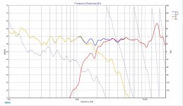
Also keen to know what the graphs of the actual system tell me in terms of what I need to do to iterate this crossover to improve the design.
Again, many thanks! Really appreciate the support.
Dear all,
So I incorporated Mr Waslo's suggestions into my simple crossover (will attempt Bills improved design next), built it and measured the result.
Hoping to get a little confirmation I'm on the right track given this is my first attempt at a complete design from ground up for me please!
Also keen to know what the graphs of the actual system tell me in terms of what I need to do to iterate this crossover to improve the design.
Again, many thanks! Really appreciate the support.
Attachments
-
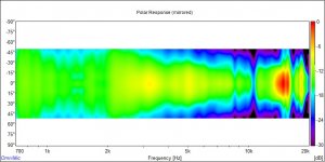 AussieWave Mini EV8L Polar.jpg55.1 KB · Views: 170
 -
AusWave B2 v2.dxo326.5 KB · Views: 58
-
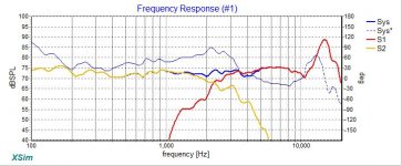 AussieWave B2 v2 Freq Resp.jpg56.6 KB · Views: 161
 -
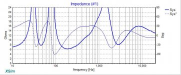 AussieWave B2 v2 Freq Imp.jpg61.1 KB · Views: 148
 -
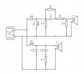
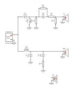 AussieWave B2 v2 Crossover.jpg15.1 KB · Views: 138
 -
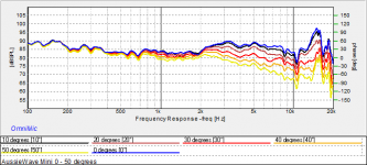 AussieWave Mini EV8L 0 - 50 degrees.png15.9 KB · Views: 162
Last edited:
Myself, I think the tweeter is still too hot, and maybe the woofer is not loud enough. Is this the only woofer available? Could you find another woofer that would have more output?
The impedance is pretty wild.
Also, would need to add a notch high up at 16kHz to kill that breakup.
The impedance is pretty wild.
Also, would need to add a notch high up at 16kHz to kill that breakup.
Agreed that the tweeter seems hot (maybe the driver measurements were off a bit?). Or you have the wrong value parts in there for R2 or C4 maybe. The modeled impedance looks just fine to me, unless you plan to use a poor damping factor tube amp or the like.
I'd personally leave that low end rise just as it is (if it's accurate, that's down where it gets hard to measure).
I'd personally leave that low end rise just as it is (if it's accurate, that's down where it gets hard to measure).
Gents thanks for your comments.
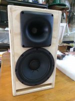
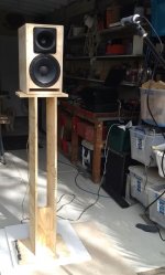
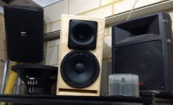
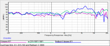
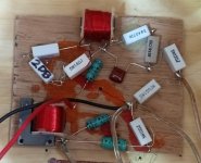
These speakers actually seem quite tame in the treble. In one of my attached pics you will see my creation, an EV ZX1i-100 and a Redback C 0996. All of these are 8" PA speakers. The Redback is a knockoff of the previous series EV SX80 which I also have (and is a great sounding loudspeaker also). I have attached a comparison sweep for these; the Redback is bright! The EV less so, then in comparison my Miniwave seems very tame to both (to my old ears). So it surprised me that you'd both suggest the top end is hot.
The woofer in my creation is an EV8L (in the Eminence Beta family if I'm not mistaken) and has a nominal 92 db. Its exactly the same driver that is in the ZX1i-100 (and SX80) as it so happens. The horn loaded compression driver is 106db by the specs.
Using the bass removed sweep with Omnimic I ramped up the volume on the compression driver till Omnimic was measuring around 90db.
I then measured the woofer (full range sweep) and both parallel (bass removed again) at exactly the same volume position on my amp, ie I did not change the level on the amp once set for the tweeter.
I have built a turntable that I sit a stand on, the speaker is placed on the stand.
Compared to the EV ZX1i-100 (which uses the same woofer) these sound decidedly tame on the top end - see comparison sweep taken back to back with my measurements of this system. The EV certainly measures more flat than mine, which have a bit of a dip down between 200 (if its accurate?) to 2000hz.
In my V3 of this crossover I'm actually thinking of dropping the value of L2 to 1.5 in the woofer circuit to bring up this region and upping the top end a little to get closer to the ZX1i-100's sound! On the other hand I'm thinking I perhaps should adjust my ears to this V2 crossovers sound for a bit to see if I like it.
Is this just a case of I'm used to the EV sound and should take a while to adjust perhaps? I will also recheck the values of all the parts in my crossovers (that's a fire breathing dragon my 6 yr old added to my crossover ply prior to assembly!).
May I assume you see no other glaring problems here?
Thanks again!
Attachments
Last edited:


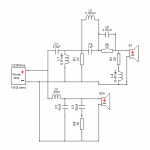
attempting a sim for 3 way build- 3 woofers in parallel, with extra inductor on lower woofer. Having a few probs .. as I'm sure you can see. Can I get away with that woofer low pass? View attachment 765114 View attachment 765115 View attachment 765116
Well, if that's real, I guess so. But how is the impedance staying above 4 ohms with 3 woofers in parallel?? Are those 16 ohm drivers or something? Maybe show the impedance curve for the woofers alone
- Home
- Design & Build
- Software Tools
- XSim free crossover designer